|
| |
TRUCK SERVICE MANUAL
TM 5-4210-230-14&P-1
TRANSMISSION
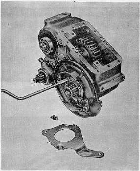
Fig. 11.
16. Remove mounting bolts and take off backing plate
assembly with washer, deflector and gasket (Fig. 11).
IMPORTANT
The front output gear cannot be removed with
the idler assembly in position because the
gears interfere with each other.
17. Remove front and rear bearing caps. Wire forward
bearing cap shims together for reassembly.
18. Remove bearing retainer plate from front end
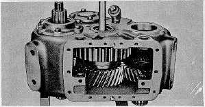
Fig. 12.
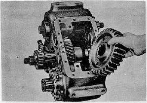
Fig. 13.
of idler shaft; then press shaft out through rear of case (Fig.
12).
19. Lift out the Lo gear, gear spacer and front bearing (Fig.
13).
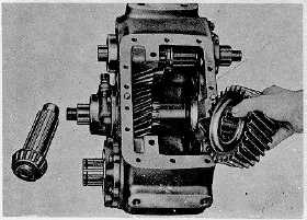
20. Remove Hi gear. Tap front bearing cup from case (Fig.
14).
21. Remove snap ring and press rear bearing from idler
shaft.
22. With idler assembly removed, the front output gear and
bearing can be removed. Remove rear bearing cap and
gasket.
23. Take off bearing snap ring and tap gear into case; reach
through cover opening and lift out gear and bearing (Fig.
15).
24. Press off radial bearing.
25. Remove capscrews and take off front and rear bearing
caps. Wire shims together for reassembly.
Fig. 14.
CTS-2048Q Page 6
PRINTED IN UNITED STATES OF AMERICA
|