|
| |
TM5-4210-229-14&P
6-18.
TRANSFER CASE REPAIR (Continued).
(2) Slip the front bearing (44) over the end of the
shaft and into the housing bore. The bearing
snapring should be on the outboard side of the
bearing. Tap bearing into place.
(3) Install the front output seal carrier gasket (52) and
the seal carrier (42) with the seal (53) in place.
Apply sealant (Appendix D, Item 47) to bolt
threads, then torque bolts(54) to 45 ft-lb (61.02
N.m).
(4) Coat the seal surface and the splined hole of the
front output yoke with Lubriplate (Appendix D,
Item 34).
(5) Align the yoke onto the shaft and tap it into place.
Lightly coat one side of the yoke retaining washer
(55) with sealant (Appendix D, Item 47) and then
install the coated side next to the yoke. Install the
locknut (56) and torque it to 300 ft-lb (406.80
N.m).
(6) Temporarily install the rear cap (43) in place
without shims (57). Torque bolts (58) to 25 ft-lb
(33.80 N.m). Measure gap between the case
housing and the flange of the cap (43). Select a
shim stack that is 0.010 to 0.15 inch larger than
the gap dimensions measured. Remove the bolts
(58) and cap (43) and then install the selected
shims and reinstall the cap. Coat bolt threads
with sealant (Appendix D, Item47), install and
torque bolts (58) to 45 ft-lb (61.02 N.m).
(7) Make certain the bearings are pulled tight against
the shaft shoulders and that the shaft rotates
freely, do this by spinning the shaft.
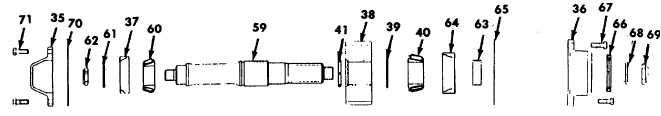
c.
Rear output shaft assembly.
(1) Install the split retaining ring (41) onto the shaft
(59). (If removed at disassembly).
(2)
Press the front bearing cone (60) tight against the
shaft shoulder and then install the washer (61) and
locknut (62). Torque the locknut to 300 ft-lb (406.80
N.m).
(3)
Coat the splined bore of the gear (38) with
Lubriplate (Appendix D, Item 34).
(4)
Lower the rear output gear (38) into the case with
the flat face against the back wall of the case and
the chamfered side toward the front of the case.
(5)
Coat the shaft splines with Lubriplate (Appendix D,
Item 34).
(6)
Insert the shaft through the proper hole in the front
of the case and align the shaft splines with the gear
splines. Protect the threaded end of the shaft and
tap the shaft into the gear until the retaining ring
seats in the chamfer of the gear.
(7)
Install the spacer ring (39).
Use heat-resistant gloves when working with high
temperatures.
(8) eat the rear bearing cone (40) to approximately 250°
(121° C). Handle bearing with heat resistant gloves
and install quickly after heating, tapping it into place
if necessary.
(9) Install the spacer tube (63) onto the shaft (59).
(10) Move the shaft toward the front of the case to
visually inspect the mating parts.
(11) Install the front bearing cup (37) and the rear
bearing cup (64) allowing the rear cup to remain
projecting between 3/8 inch and1/4 inch from the
case.
(12) Install the rear output carrier gasket (65) and the
rear output carrier (36) along with seal (66). Coat
retaining bolt threads in sealant (Appendix D, Item
47), install and torque bolts (67) to 45 ft-lb (61.02
N.m).
6-100
|