|
| |
TM5-4210-229-14&P
6-18.
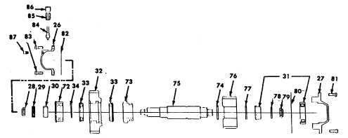
TRANSFER CASE REPAIR (Continued).
e.
Input shaft disassembly.
(1)
Remove the rear cover (16) and the front seal
carrier (17).
(2)
Use a brass rod or aluminum bar to protect the
end of the shaft, tap threaded end
f.
Intermediate shaft removal.
(1)
Remove the capscrews from the front cap(26)
and the rear cap (2 7). Remove the front
speedometer cap (26), nut (28), speedometer
drive gear (29) and spacer (30).Screw alignment
tool on to the end of the shaft. Place alignment
studs in two holes of the rear cap (27). Drive on
end of alignment tool until the rear cap (27) is
clear of the case housing. Remove the cap along
with the outer race and roller assembly of
bear-ing (3 1). Block between the under drive
gear( 32) and the rear of the case. Continue to
drive the alignment tool until the shaft is
enough to place the direct drive gear (18)just
against the inside back wall of the transfer case
housing. Slide the under drive pinion gear (19)
toward the front of the case, exposing the split
retaining ring (20).Use a drift to drive the retaining
ring from the shaft.
(3)
Tap on the rear end of the shaft and remove the
shaft and the front bearing (21) at the front of the
case. Since the bearings (22)and (23) are press
fitted on the shaft, the shaft will not slip out easily.
(4)
The gears (18 and 19), clutch (24), washer(25) and
the bearing (23) can now be re-moved from inside
the
case.
free of the gear (32) and the transfer case.
Remove the gear (32) with bearing (33) still in
phase and the spacer ring (34) from in-side the
case.
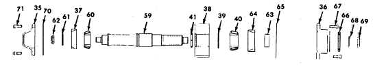
g.
Rear output shaft removal.
(1)
Remove the front cover (35) and the rear cover
(36). Tap the output end of the shaft(rear end of
shaft) and remove bearing cup(37) from the front
of the case. Block between the gear (38) and
the case while continuing to drive the shaft out of
the front of the case.
(2)
Remove the gear (38), spacer ring (39) and
bearing cone (40) from inside the case.
(3)
Remove split ring (4 1) from the shaft only if it is
being replaced.
6-97
|