|
| |
TM5-4210-229-14&P
6-15.
TRANSMISSION REPAIR (Continued).
clearance is still excessive after all eight
plates and the backplate have been
replaced, a thicker piston (229) is required.
(g) If the clearance is insufficient (first step of
gauge will not fit), a thinner piston (229) is
required.
(h) Install the piston return spring (224) and
spring retainer (222). Using compressor
tool and compressor base, depress the
spring retainer (222). Install the snapring
(223) to retain the spring retainer (222).
(i) Install the bearing race (221) outer lip first,
onto the rear hub of the clutch housing.
Use oil-soluble grease (Appendix D, Item
21) to retain the races during subsequent
assembly.
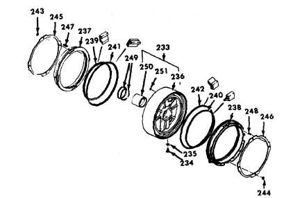
g. Center support assembly repair.
(1) Disassembly.
(a) Place center support assembly (233)
vertically (upright), on the work table.
(e) If
parts
replacement
is
necessary,
disassemble the two piston assemblies.
Cut the self-locking retainer rings (243 and
244) to prevent damaging the piston
projections, Remove four self locking
retainer rings (243 and 244), a retainer
(245 or 246) and twenty springs (247 or
248) from each piston (237 or 238).
(f) Remove two sealrings (249) from the hub
of the center support assembly.
(g) If the bushing (250) in the center support is
worn or damaged, collapse the bushing
(250) inward at the bushings splitline and
remove.
(h) Remove the ball (25 1) freed by removing
the bushing (250) from the hub of the
support (236).
(i) Determine the serviceability of the sealring
grooves on the center support hub. Insert,
do not force, gauge into the groove on the
center support hub. Rotate the gauge 360
degrees around the hub. If the gauge does
not rotate freely, the support is damaged
and should be replaced.
(b) Remove oil filter (234) and sealring (235)
from center support (236).
(c) Remove pistons (237 and 238) with
attached parts.
(d) Remove the inner sealrings (239 and 240)
and outer sealrings (241 and 242) from
each piston.
6-71
|