|
| |
TM5-4210-229-14&P
6-15.
TRANSMISSION REPAIR (Continued).
(a)
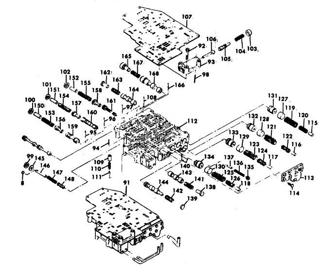
Place valve assembly (91) on the work
table, modulator valve body (93) upward.
(b)
Remove three bolts (92) from the
modulator body (93) and remove the
modulator body (93).
NOTE
Before removing pins (94, 95, 96, 97, and 98),
make a note or sketch that shows the position of
adjusting rings (99, 100, 101, 102 and 103) in
respect to their retaining pins. If the valve body is
reassembled with the same springs, and the
adjusting rings are in their original positions, the
original
calibration
of
the
valve
body
is
maintained.
(c)
Remove retaining pin (98) from modulator
body (93) while applying pressure to adjusting
ring (103). Remove the adjusting ring (103).
(d)
Remove spring (104), valve (105), and
actuator pin (106).
(e)
Remove separator plate (107). A slot is
included in the separator plate that engages
the flared end of retaining pin (108). The
separator plate must be slid lengthwise to
disengage it from pin (108).
(f)
Remove priority valve (109), spring (110) and
stop (111).
(g)
Place control valve body (112) on the work
table, flat side down.
6-58
|

