|
| |
TM5-4210-229-14&P
5-23. POWER STEERING GEAR REPAIR (Continued).
e.
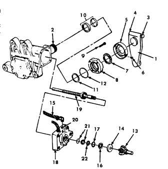
Position catch basin beneath gear to protect
against fluid spill during removal of trunnion cover
(8).
f.
Remove four trunnion cover bolts (9) and trun-
nion cover (8).
g.
Remove two-piece sector shaft seal (10), teflon
backup washer (11) and trunnion cover sealring
(12).
Cleaning solvent (Appendix D, Item 54) is both
toxic and flammable. Keep off skin. Use only in
a well-ventilated area and avoid prolonged
breathing of vapors. Keep away from open
flames.
h.
Clean trunnion cover (8) with solvent (Appendix
D, Item 54).
i.
Mark to assure proper alignment during as-
sembly remove input coupling (13) and seal
protector (14). If coupling (13) is tight, insert
screwdriver into slot to release.
j.
Clean the area around the input shaft using fine
emery paper (Appendix D, Item 13).
k.
Remove and plug the return line (15).
l.
Remove and discard seal (16) and remove seal
retaining ring (17) from the valve housing (18).
Compressed air used for cleaning or drying can
create airborne particles that may enter the eyes.
Pressure shall not exceed 30 psi (206 kPa).
Wearing of goggles is required to avoid injury to
personnel.
m.
Hold a piece of cloth (Appendix D, Item 14) over
the worm shaft/input shaft (19) and apply air pressure to
the valve housing return port (20). This will force the
two piece input shaft seal (21) and steel backup washer
(22) to pop out of the gear. Discard the two piece seal.
REPAIR
Repair consists of replacing damaged or defec-
tive components.
ASSEMBLY
a.
Apply grease (Appendix D, Item 22) to the new
input shaft seal (21) and steel backup washer (22)
and to the input shaft (19).
b.
Install the two piece seal (21) flat side up and the
steel backup washer (22) using seal driver.
c.
Install retaining ring (17).
d.
Pack the area around the input shaft with high
temperature grease (Appendix D, Item 22).
e.
Install the new seal (16) using the seal driver.
f.
Add more grease (Appendix D, Item 22) and
assemble seal protector (14) onto worm shaft/
input shaft (19) seating it in the relief groove just
beyond the input shaft serrations with cup side
toward the gear.
g.
Remove plug in return line (15) and reconnect the
return line to the steering gear.
h.
Reconnect input coupling (13) aligning marks
properly.
5-55
|


