|
| |
TM5-4210-229-14&P
5-13.
STARTER REPAIR. (Continued).
c.
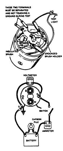
Test series coil for ground.
Using a test lamp, place one lead on the
grounded brush holder and the other lead on
either insulated brush. If the lamp lights, a
grounded series coil is indicated and must be
repaired or replaced.
d.
Testing solenoid windings.
(1)
If solenoid is not removed from starting motor,
the
connector
strap
terminals
must
be
removed from the terminal on the solenoid
before making these tests. Complete tests in
a minimum of time to prevent over heating of
the solenoid.
(2)
To
check
hold-in
winding,
connect
an
ammeter in series with 12 volt battery and the
switch terminal on the solenoid. Connect a
voltmeter to the switch terminal and to
ground. Connect carbon pile across battery.
Adjust the voltage to 10 volts and note the
ammeter reading. It should be 14.5 to 16.5
amperes for all starting motors.
(3)
To check both windings, connect as for
previous test. Ground the solenoid motor
terminal. Adjust the voltage to 10 volts and
note the ammeter reading. It should be 41 to
47 amperes for all starting motors.
NOTE
Current will decrease as windings heat up.
(4)
Current
draw
readings
that
are
over
specifications indicate shorted turns or a
ground in the windings of the solenoid and the
solenoid should be replaced. Current draw
readings that are under specifications indicate
excessive resistance. No reading indicates
an open circuit. Check connections then
replace solenoid if necessary.
ASSEMBLY
a.
Lubricate drive end of armature shaft (1) with
lubricant (Appendix D, Item 32).
b.
Install center bearing (2) with bearing toward the
armature winding. Then install the fiber washer (3)
on the armature shaft (1).
c.
Slide clutch assembly (4) onto armature shaft (1)
with pinion away from armature (5).
d.
Slide retainer (6) onto shaft (1) with cupped side
facing the end of shaft (1).
5-34
|