|
| |
TM5-4210-229-14&P
5-12.
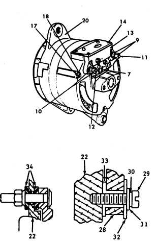
ALTERNATOR REPAIR (Continued).
n.
Using a bearing puller remove drive end housing
(20) and bearing assembly (35) from the rotor shaft
(19).
o.
Remove four screws (36) and bearing retainer (37)
and press bearing out of drive end housing.
p.
With a heat gun, remove wire (38) that connects the
rotor coil (19) to the outside slip ring (39). Unsolder
the wire from the inside slip ring (40) and with a
bearing puller, remove the slip ring assembly and
insulation washer (41).
q.
Using a bearing puller, remove the bearing (42).
TEST
NOTE
Before performing these tests, inspect all parts
for wear, cracks, or other mechanical defects.
Replace all damaged parts.
a.
Positive heat sink test.
NOTE
The positive heat sink is the one to which
positive output terminal is connected. The
square hole in the positive heat sink is larger
than the negative heat sink hole.
(1)
Connect the positive lead of the test lamp to
the positive heat sink and touch the negative
test lead to each of the three diode terminals.
The test lamp should not light. If the test
lamp lights, the diode is shorted.
(2)
Reverse the test leads so that the negative
test lead is connected to the positive heat
sink. The positive test lead should now be
touched to each diode terminal. If the test
lamp fails to light, an open diode is indicated.
(3)
If a shortened or open diode is detected,
replace the entire heat sink assembly.
b.
Negative heat sink test.
(1)
Connect the negative lead of the test lamp to
the negative heat sink and touch the positive
test lead to each of the three diode terminals.
The test lamp should not light. If the test lamp
lights, the diode is shorted.
(2)
Reverse the test leads so that the positive test
lead is connected to the negative heat sink.
The negative test lead should now be touched
to each diode terminal. If the test lamp fails to
light, an open diode is indicated.
(3)
If a shorted or open diode is detected, replace
the entire heat sink assembly.
5-29
|