|
| |
TM5-4210-229-14&P
5-12.
ALTERNATOR REPAIR (Continued).
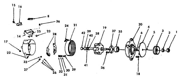
DISASSEMBLY
a.
Remove the shaft nut (1) and washer (2).
b.
Using the bearing puller, remove the pulley (3), fan
(4), drive key (5), and fan spacer (6).
c.
Remove the diode lead (7) from top of the regulator
(8) and remove the 5/16-18 (9) and 1/4-20 nuts (10)
from the positive and negative output terminals (11
and 12) which will free the regulator jumpers for the
regulator and brush housing assembly (13) removal.
NOTE
Due to the application of Loctite to the brush
housing screws during manufacturing, it may be
necessary to apply heat to assist in the removal
of these screws. Use a heat gun and hold on
each screw for approximately 45-60 seconds.
d.
Remove four 8-32 screws (14) and remove
regulator and brush housing assembly (13).
e.
Remove three screws (15) and remove diode trio
(16) from AC terminal board.
f.
Remove three lock nuts (17) and through bolts (18).
Ensure that drive end housing (20) separates from
stator (21) and that the stator remains attached to
the slip ring end housing (22) to avoid damage to
the stator leads.
g.
Remove rotor (19) and drive end housing assembly
(20) from stator (21) and slip ring end housing
assembly (22).
h.
Remove three nuts (23) which secure stator leads
(24) to terminals (25) and remove stator (21).
i.
Remove positive and negative output terminal bolts
(11 and 12).
j.
Remove three hex screws (26) and remove
capacitor (27) connected between the heat sinks
(28).
k.
Remove two screws (29), lockwashers (30), guard
washers (31), and insulating washers (32) which
retain lower end of heat sinks (28).
l.
Remove heat sinks (28) and note location of
insulating washers (32) and bushings (33).
m. Remove two terminal stud bushings (34).
5-28
|

