|
| |
TM5-4210-229-14&P
5-6. HYDRAULIC RESCUE TOOL POWER UNIT REPAIR (Continued).
REASSEMBLY
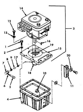
a.
Reassembly of Hydraulic Rescue Tool Power
Unit.
(1)
Place ball (8) and spring (9) back into
pump housing (18) making sure the spring
seats
properly.
(2)
Install the relief valve fitting (7) and tighten
so that hole is at a 35° angle to the bottom
of the pump housing.
(3)
Install gasket (6).
(4)
Torque relief valve subassembly (5) to
approximately 25 ft-lb (34 N.m).
(5)
Install engine key (16) in proper position on
engine shaft.
(6)
Align engine key (16) with slot in engine
pump adapter (19) and carefully slide
engine (14) into proper position on cover
plate assembly (15).
(7)
Install
three
engine
bolts
(12)
and
lock-washers (13).
NOTE
No seal rings should be located inside the reservoir.
(8)
Position new liquid level gauge (11) on
reservoir (4) making sure the red line is
toward the bottom and that the six seat
rings (20) are properly positioned.
(9)
Install two locknuts (10) and hand tighten.
(10) Torque two bolt heads on liquid level
gauge (11) to 10 ft-lb (13.6 N.m).
(11) Set power unit (3) in reservoir (4) with level
gauge facing same direction as dump
valve .
(12) Secure
with
ten
screws
(1)
and
lock-washers (2). Torque screws (1) to 10
ft-lb (13.6 N.m).
5-9
|

