|
| |
TM5-4210-229-14&P
4-37. HOSE REEL ASSEMBLY MAINTENANCE (Continued).
b.
Secure hose reel to frame with four bolts (16),
lockwashers (15) and nuts (14).
c.
Position rear control panel (12) to hose reel (13)
and secure with three bolts (11), lockwashers (10),
and nuts (9).
d.
Connect streetside hose (7) to swivel joint (8).
e.
Connect curbside hose (5) to inlet elbow (6).
f.
Attach control wiring (3) to solenoid (4) and secure
with lockwashers (2) and nuts (1).
g.
Attach dual agent handline hoses (paragraph 4-40).
h.
Install nitrogen cylinders paragraph 4-16) and pres-
surize system (paragraphs 2-24 or 2-25).
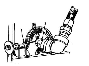
SERVICE
a.
Lubricate grease fitting (1) on the brake handle
assembly. Pressure gun should be held on the fit-
ting until grease appears.
b.
Lubricate grease fitting (2) on the swivel joint.
Pressure gun should be pumped approximately
five times for proper servicing.
4-38. HOSE ROLLERS REPLACEMENT.
This task covers:
a.
Removal
b. Installation
INITIAL SET-UP
Tools
General Safety Instructions
General Mechanics Tool Kit
Engine OFF.
Transmission in (N) neutral.
Materials/Parts
Parking brake set.
Hose Rollers (R-281)
Equipment Condition
Para.
Condition Description
2-23
Pressure Relieved in System
4-53
|

