 |
|||
|
|
|||
|
|
|||
| ||||||||||
|
|
 TM5-4210-224-14&P
5-10.
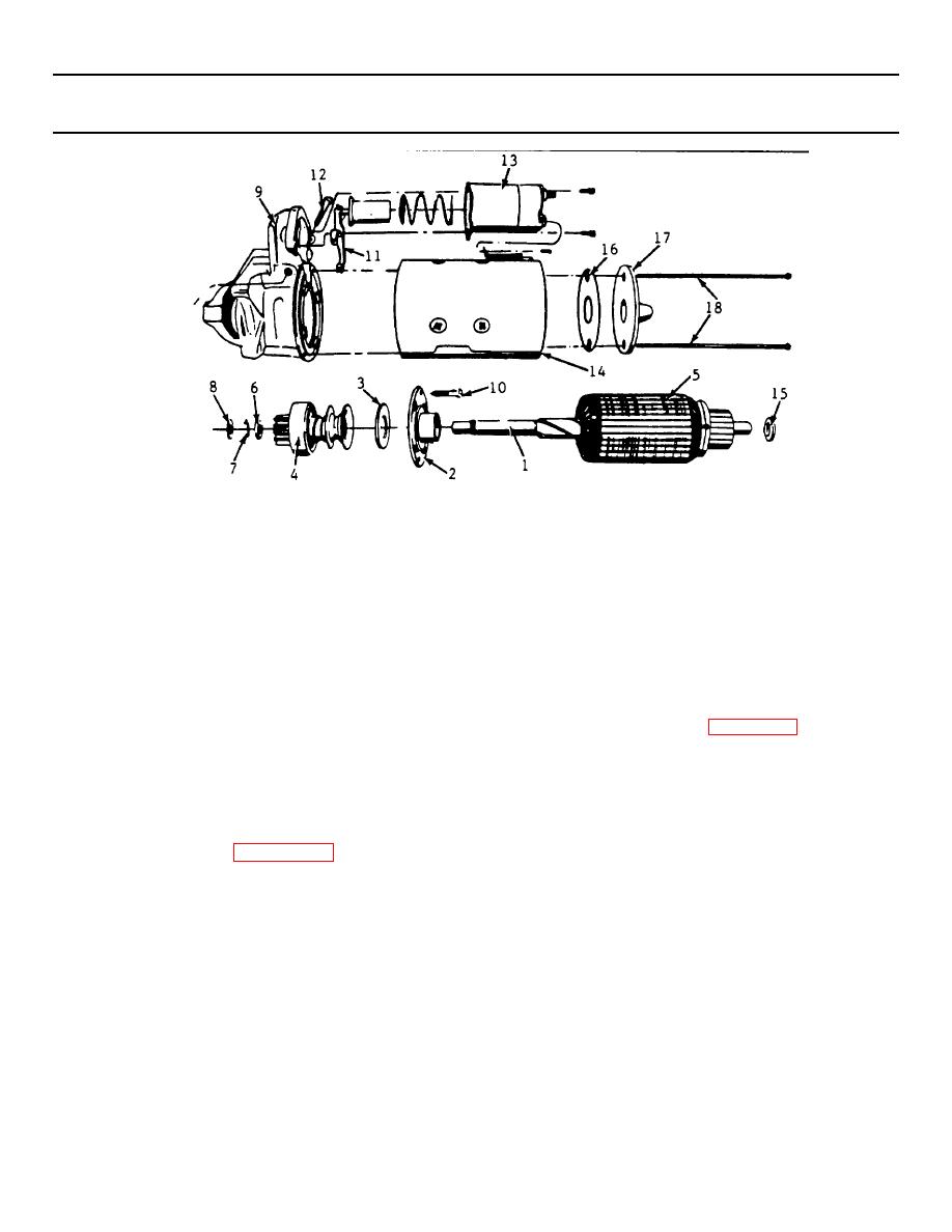
STARTER REPAIR. (Continued)
(9) Engage shift lever yoke with clutch and
(3) Slide clutch assembly (4) onto armature
slide complete assembly into drive gear
shaft (1) with pinion away from armature
housing (9).
(5).
(10) Install the cener bearing screws (10) and
t
(4) Slide retainer (6) onto shaft (1) with
the shift lever (11), and pivot bolt (12).
cupped side facing the end of shaft (1).
(11) Install solenoid assembly (13).
(12) Position field frame (14) against drive
(5) Install snap ring (7) into groove on
gear housing (9) on alignment pin using
armature shaft.
care to prevent damage to brushes.
(6) Install thrust washer (8) on shaft (1).
(13) Lubricate commutator endframe bushing
with lubricant (Appendix D, Item 17).
(7) Position retainer (6) and thrust washer (8)
with snap ring (7) in between. Using two
(14) Install washer (15) on armature shaft and
pliers, grip retainer (6) and thrust washer
slide end frame onto shaft (1). Install
(8) or collar and squeeze until snap ring
insulator (16) and then end frame (17)
(7) is forced into retainer (6) and is held
onto shaft (1). Then install through-bolts
securely in groove in armature shaft (1).
(18) making sure they pass through bolt
holes in insulator (16).
(8) Lubricate (Appendix D, Item 17) drive
gear housing bushing.
(15) Connect the field coil connector (15) to
the solenoid terminal with screw (20).
5-25
|
|
Privacy Statement - Press Release - Copyright Information. - Contact Us |
