 |
|||
|
|
|||
|
|
|||
| ||||||||||
|
|
 TM5-4210-224-14&P
5-10.
STARTER REPAIR. (Continued)
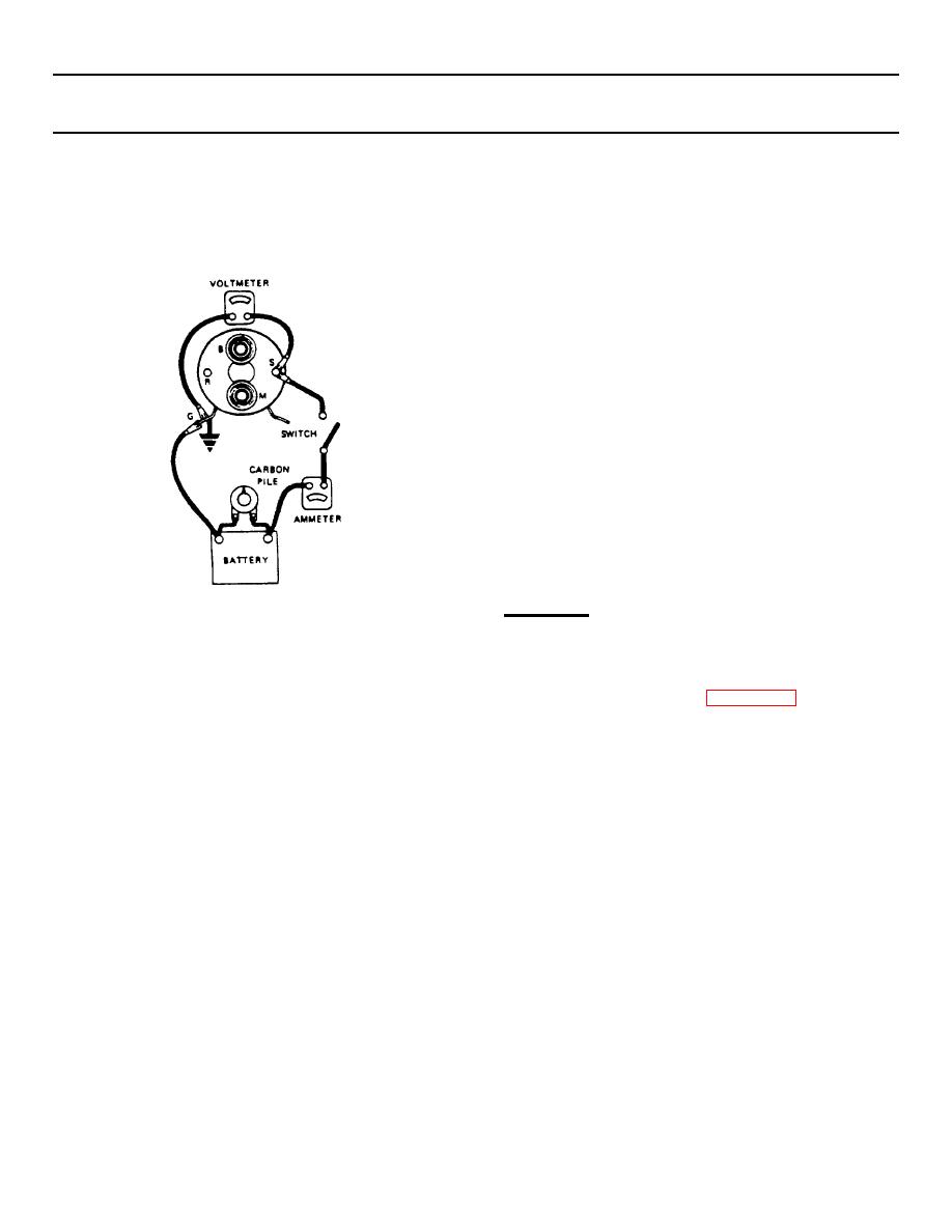
motor, the connector strap terminals must
terminal. Adjust the voltage to 10 volts
be removed from the terminal on the
and note the ammeter reading. It should
solenoid before making these tests.
be 41 to 47 amperes for all starting
Complete tests in a minimum of time to
motors.
prevent overheating of the solenoid.
NOTE
Current will decrease as windings heat
up.
(d) Current draw readings that are over
specifications indicate shorted turnes or a
ground in the windings of the solenoid and
the solenoid should be replaced. Current
draw
readings
that
are
under
specifications
indicate
excessive
resistance. No reading indicates an open
circuit. Check connections then replace
solenoid if necessary.
ASSEMBLY
(2) To check hold-in winding, connect an
Assemble the armature and clutch as follows:
ammeter in series with 12-volt battery and
the "switch" terminal on the solenoid.
(1) Lubricate drive end of armature shaft (1)
Connect a voltmeter to the "switch"
with lubricate (Appendix D, Item 17).
terminal and to ground. Connect carbon
pile across battery. Adjust the voltage to
(2) Install center bearing (2) with bearing
10 volts and note the ammeter reading. It
toward the armature winding. Then install
should be 14.5 to 16.5 amperes for all
the fiber washer (3) on the armature shaft
starting motors.
(1).
(3) To check both windings, connect as for
previous test. Ground the solenoid motor
5-24
|
|
Privacy Statement - Press Release - Copyright Information. - Contact Us |
