 |
|||
|
|
|||
|
Page Title:
IGNITION SWITCH AND TONE ALARM REPLACEMENT. |
|
||
| ||||||||||
|
|
 TM 5-4210-224-14&P
4-147. IGNITION SWITCH AND TONE ALARM REPLACEMENT.
This task covers:
a. Removal
b. Installation
INITIAL SETUP:
Tools
General Safety Instructions
General Mechanics Tool Kit
Engine OFF.
Transmission in (N) neutral.
Materials/Parts
Parking brake and micro-brakelock set.
Batteries disconnected.
Switch (1990115)
NOTE
REMOVAL
Actuating rod to the switch should
be pulled up until there is a definite
CAUTION
stop, then moved down one detent,
Be sure that the steering column is
which is the "lock" position.
properly supported if it is not
removed from the vehicle.
a.
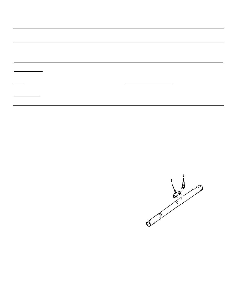
Place the ignition switch (1) in the "lock"
position.
NOTE
The ignition switch is mounted on
b.
Remove the two ignition switch screws (2).
top of the column jacket near the
front of the dash. For anti-theft
c.
Remove the ignition switch assembly.
reasons, the switch is located
inside the channel section of the
brake pedal support. The switch is
actuated by a rod and rack
assembly. A portion of the rack is
toothed and engages a gear on the
end of the lock cylinder.
This
enables the rod and rack to be
moved axially (with respect to the
column) to actuate the switch when
the lock cylinder is rotated.
It is not necessary to remove the
steering wheel when following this
procedure.
4-201
|
|
Privacy Statement - Press Release - Copyright Information. - Contact Us |
