|
| |
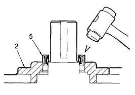
TM 5-4210-220-34
2-12.
PUMP DRIVE AND PTO - Continued
(7)
Inspect capscrews (1) and housing (3) threads. Replace capscrews as necessary.
(8)
If working on an open cap (2) remove the oil seal (5).
(9)
Clean the cap (2) and housing (3) gasket area.
(10) Install new gaskets (4) onto cap (2). Be sure to install the same number of gaskets as recorded in step (6)
preceding. If unsure about the number of gaskets Install three gaskets under one cap. Do not apply gasket
glue.
(11) Aline cap, gaskets, and housing screw holes and attach cap (2) to housing (3) using capscrews (1). Torque
capscrews (1) evenly to 28 ft lb (38 Nm). While tightening the capscrews, rotate the respective shaft and
stop tightening at the first sign of binding or resistance.
NOTE
Shaft end play is adjusted by adding or deleting cap gaskets (4) until the shaft rotates freely, with no end
play.
(12) If end play is evident remove one gasket at a time and repeat step 10 and 11 preceding.
(13) If shaft is binding, add one gasket at a time and repeat step 10 and 11 preceding.
(14) When end play is correct, remove and clean capscrews (1) and housing threaded holes.
(15) Apply threadlock liquid (item 29, Appendix B) to capscrew (1) and reinstall into housing.
(16) Evenly torque capscrews (1) to 28 ft lb (38 Nm) Rotate respective shaft while tightening to ensure bearings
do not bind.
CAUTION
To avoid seal damage during installation, cover the shaft keyway with paper or cellophane tape before
sliding the seal onto the shaft.
(17) Cover shaft keyway using cellophane tape
to avoid seal damage during installation.
(18) Install seal (5) onto shaft. Make sure the
spring loaded lip of the seal is facing the
reducer gear box.
(19) Using a soft faced hammer, carefully tap
seal (5) into cap (2). Stagger the tapping
over the circumference to ensure seal is
installed evenly.
(20) Install gearbox in truck as detailed in TM 5-
4210-220-12.
2-87
|