|
| |
TM 5-4210-220-34
2-12.
PUMP DRIVE AND PTO - Continued
2-12.2
PTO To Reducer Gear Drive Shaft - Continued
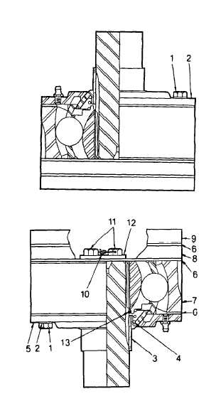
(13) Stack disc joint components on bench as
shown. Aline capscrew holes.
(14) For slipping disc joint only, install washers (2)
onto capscrews (1) and apply threadlock liquid
(item 29, Appendix B) to threads. Install
capscrews and tighten to 95 ft lb (130 Nm).
Go to step 23.
(15) For locking disc joint only, carry out steps 16
thru 22. Assembly is easier if drive shaft is in
a vertical position.
(16) Install wiper (5), mechanical seal (3), and snap
ring (13) onto splined shaft.
(17) Install spring (4) and one gasket (6). Aline
shaft splines with disc joint (7) and install.
(18) Apply threadlock liquid (item 29, Appendix B) to
capscrews (11).
(19) Attach retainer (12) to shaft using capscrews
(11). Tighten capscrews to 40 ft lb (54 Nm).
(20) Install safety wire (10) into capscrew heads.
(21) Install gasket (6), spacer plate (8), gasket (6),
and spacer plate (9) onto disc joint. Aline all
capscrew holes.
(22) Install washers (2) onto capscrews (1) and
apply threadlock liquid (item 29, Appendix B)
to threads. Install capscrevvs (1) and tighten
to 95 ft lb (130 Nm).
(23) Aline slipping disc joint assembly with splined shaft
(24) Refer to Lube Order LO 5-4210-220-12, for lubrication instructions.
2-80 (2-81 Blank)
|

