|
| |
TM 5-4210-220-34
2-11.
HOSE BODY - Continued
2-11.3
Compartment Boxes - Continued
e.
Right-Hand Compartment Assembly Repair
NOTE
To
disassemble
the
right
hand
compartment
assembly, it must first be separated from the hose
body assembly. To separate the right hand
compartment
assembly
remove
the
following
subassemblies
Compartment Tops (see a. preceding) Hose Bed
(see b. preceding) Front Panel Assembly (see c.
preceding) Rear Panel Assembly (see d. preceding)
(1)
Separate
the
upper
panel
from
the
compartment
boxes
by
removing
lockbolts.
(2)
Separate
the
lower
panel
from
the
compartment
boxes
by
removing
lockbolts.
(3)
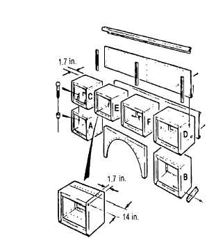
Remove lockbolts that retain the box assemblies as a group. Separate the boxes from each other by
removing lockbolts. Using illustration, remove compartment boxes in alphabetical order. Do not
remove rivets because they hold the compartment panels together.
(4)
Replace fender skirt as necessary, see para. 2-11.1.
NOTE
Apply sealant (item 25, Appendix B) to all metal mating surfaces prior to installation.
(5)
To assemble the right-hand compartment assembly, attach four center boxes (C, E, F, D) as shown.
Make sure boxes are in correct order and that the tops are level. Lockbolt boxes together.
(6)
Measure and scribe a vertical line 1.7 in. (4.3 cm) as shown on compartment (C) rear panel.
Position lower panel so that it is level with compartment boxes and adjacent to scribe mark.
(7)
Secure lower panel in this position using lockbolts. If lower panel is new, use holes in compartment rear
panels as drill templates.
(8)
Aline compartment (A) beneath compartment (C) and attach using proper lockbolts. Replace splash
guard, see para. 2-11.1.
(9)
Install fender skirt under boxes (E and F). Secure fender skirt to compartment boxes (A, E, and F) using
lockbolts. If compartment boxes are new, use fender skirt as a drill template.
(10) Aline compartment (B) beneath compartment (D) and attach using lockbolts. If compartment (B) is new,
replace main body angle. Fasten to compartment using lockbolts.
2-60
|