|
| |
TM 5-4210-220-34
2-11.
HOSE BODY - Continued
2-11.2
Manhole Cover and Panels.
This task covers:
a. Removal
b. Inspection
c. Installation
TOOLS
MATERIALS/PARTS
Shop Equipment, Automotive
25, Appendix B Sealant
Maintenance and Repair,
2801-06 Lockbolt
NSN 4910-00-754-0705
2667-06 Lockbolt Collar
1604-0615 Rivet
EQUIPMENT CONDITION
100080 Rear Manhole Panel
Main Engine Shutdown (see TM 5-4210-220-12)
100078 Left Manhole Panel
Batteries Disconnected (see TM 5-4210-220-12)
100079 Right Manhole Panel
NOTE
For lockbolt and collar removal/installation refer to para. 2-7. Apply 1/8 in. (3 mm) bead of sealant (item
25, Appendix B) to all metal mating surfaces, prior to installation.
REMOVAL
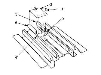
(1) Remove the machine screws (1), and
locknuts (2) that retain the manhole cover
(3) to the rear manhole panel (4). Unfasten
manhole cover strap and remove manhole
cover
(2) Remove six lockbolts that retain the rear
manhole panel (4) to the left and right
manhole panels (6 and 5), and inboard
partitions.
(3) Remove six lockbolts that retain rear
manhole panel (4) to the hose bed.
(4) Remove 11 lockbolts that retain the left
hand manhole panel (6) to the hose bed
and hose body front panel.
(5) Remove 11 lockbolts that retain the right hand manhole panel (5) to the hose bed and hose body front panel.
(6) Separate manhole panel assembly from hose bed. It will be necessary to crack or remove insulation
adhering to inner surface of manhole panels.
INSPECTION
Inspect all mounting holes for oversize or cracks. Some oversized holes can be repaired by installing a
washer during lockbolt installation. The washer will cover the hole and strengthen the joint.
2-54
|

