|
| |
TM 5-4210-220-34
2-11.
HOSE BODY - Continued
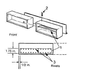
(1) To remove the stiffeners (1) remove the
lockbolts (2) and rivets (3) that retain the
stiffener and compartment top and to the
upper compartment boxes, see para. 2-7.
Each stiffener has two rivets (3) that retain
it in position while hose body is being
painted.
(2) Inspect stiffener for oversized mounting
holes, cracks or bends. Replace as
necessary.
(3) To install stiffener, position on compartment
box top as shown.
(4) Install
two
rivets
from
outside
of
compartment box. These two rivets will
retain stiffener to hose body during painting.
(5)
Install compartment top as detailed in para.
2-11.3a.
(6) Using stiffener as a template, drill mounting holes through compartment top or compartment box as
necessary.
(7) Install stiffener with lockbolts as detailed In para. 2-7.
p. Partitions.
NOTE
There are four partitions used on this hose bed assembly. Two methods of installation can be used. To
remove inboard partitions, remove lockbolts that retain the inboard partitions to the manhole panels.
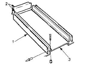
(1) To remove partition assembly, remove the rivets that retain the cover (2) to the hose bed (3).
(2) Remove the lockbolts that retain the partition (1) to the hose bed (3) (para. 2-7).
(3) To separate the cover (2) from the partition
(1) remove remaining rivets.
(4) Inspect all mounting holes for cracks,
oversized holes, or dents.
(5)
Minor bends or dents can be repaired using
basic body repair tools. NOTE If either
inboard
partition
assembly
is
to
be
replaced, leave cover (2) off. First attach
side manhole cover, rear manhole cover
and partition together. Then install cover
(2), using rivets (para. 2-7).
(6)
Position
partition
on
hose
bed,
aline
mounting holes and attach to hose bed
using lockbolts, (para. 2-7). If hose bed is
new, use partition as a drill template
(7) Attach cover to partition using rivets (para. 2-7). If hose bed is new, use cover as a template
2-53
|