|
| |
TM 5-4210-220-34
2-11.
HOSE BODY - Continued
2-11.1 Hose Body Assembly - Continued
b.
Hose Bed Matting Repair
NOTE
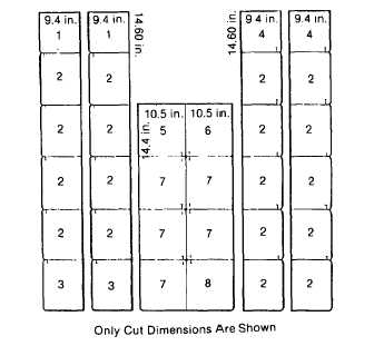
Repair to tiles is limited to replacement
of any that are damaged. Tiles are
originally 19.38 in. square (49.23 cm
square).
Remove
all
hoses
from
appropriate hose bed prior to replacing
tiles. Before cutting tiles, determine
position and orientation. This will ensure
that all tiles will interlock when installed.
(1) Cut tiles with hacksaw. Use the illustration
to obtain measurements and orientation.
(2) Install new tile.
c.
Compartment Drain
NOTE
There are four compartment drains on hose body assembly, one in each lower compartment box floor.
Repair to compartment drains includes replacement of dust valve, gear clamp or drain adaptor.
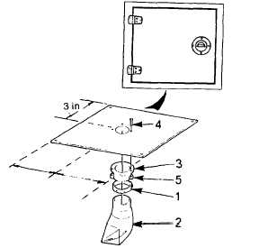
(1) Remove gear clamp (1) and dust valve (2)
from drain adaptor (3).
(2) Inspect gear clamp, dust valve and drain
adaptor for damage. Replace parts as
necessary.
(3) To remove drain adaptor (3) remove
lockbolts (4) and lockbolt collars (5) as
detailed in para. 2-7.
(4) Apply sealant (item 25, Appendix B) to
perimeter
of
drain
adaptor
prior
to
installation.
(5) Secure
new
drain
adaptor
(3)
to
compartment box using lockbolts (4) and
lockbolt collars (5). Refer to para. 2-7 for
lockbolt installation.
NOTE
If compartment box is new, position drain adaptor (3) as shown. Drill 1 in. (2.54 cm) hole. 2-46
(6)
Install dust valve (2) onto drain adaptor (3) and secure using gear clamp (1). Tighten gear clamp firmly.
2-46
|