|
| |
TM 5-4210-220-34
2-11.
HOSE BODY - Continued
(15) Lower hinged step from step lock and inspect contact area on pump body angle.
(16) Install all hoses in to proper hose bed
(17) Install all auxiliary equipment into appropriate compartments.
(18) Tie or support all hoses, wiring and linkages so they will not be damaged during normal operation.
(19) Install heat shields (see TM 5-4210-220-12).
(20) Refill radiator and winterization heater system as detailed in LO 5-4210-220-12 Start APU, bleed system and
check for leaks. Tighten/remake connections as required
(21) Fill water and foam tank to ’FULL’ level as detailed in TM 5-4210-220-12. Inspect for leaks Tighten/remake
connections as necessary.
(22) Refer to TM 5-4210-220-12 to ensure all components are operating correctly
REPAIR
a.
Grab Handle Repair
NOTE
Grab
handle
repair
is
limited
to
replacement of grab
handle,
machine
screws,
or
insert
fasteners.
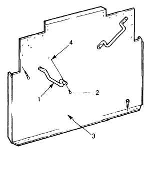
(1) To remove grab handle (1), remove four
machine screws (2). Separate grab handle
from rear panel (3)
(2) Inspect machine screws (2) and insert
fasteners (4) as detailed In para. 2-7.
Replace parts as necessary.
(3) To Install grab handle (1), lift into position
and
aline
mounting
holes
with
insert
fasteners (4).
(4)
Install machine screws (2) and tighten
firmly.
2-45
|

