|
| |
TM 5-4210-220-34
3-8.
ENGINE - Continued
g.
Cylinder Block Deck Surface Inspection
(1) Check head contact area of block for flatness
with block straight edge and feeler gage.
(2) Block should not vary more than 0.003 in.
(0.008 mm) transversely or 0.006 in. (0.15
mm) longitudinally.
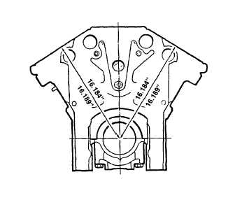
(3) Distance from centerline of crankshaft to top
of block/head surface must be between
16.184 in. and 16.189 in. (411.07 - 411.20
mm). If block is not within specification, it
must be replaced.
h.
Cylinder Counterbore Inspection
WARNING
Death or serious injury could occur if compressed air is directed against the skin. Do not use compressed
air for cleaning or drying unless the pressure Is/has been reduced to 30 psi (2.11 kg/cm2) or less. When
working with compressed air always use chip guards, eye protection and other personal protective
equipment.
(1)
Thoroughly clean cylinder liner counterbores. Blow area clean with compressed air.
(2)
Measure counterbore depth. Counterbore depth must be 0.4755 0.4770 in. (12.078 12.116 mm) or 0.4905
0.4920 in. (12.459 12.497 mm) and must not vary more than 0.0015 in. (0.038 mm) throughout the entire
circumference. There must not be over 0.0015 In. (0.038 mm) difference between any two adjacent cylinder
counterbores when measured along the cylinder longitudinal center line of the cylinder block.
j.
Block Bolt Hole Threads Inspection
(1) Inspect cylinder head and main bearing cap bolt holes. If threads are damaged, use a tap to clean up the
threads or Install a helicoil thread insert.
(2) An insert thread repair kit, J29513, is available for installing an 11/16 in. - 11 helicoil thread insert in the
cylinder head and main bearing cap retaining bolt holes of the cylinder block.
INSTALLATION
(1) Install all oil gallery and core hole plugs removed for cleaning procedure. Use pipe sealant (item 22,
Appendix B) on all threads.
(2) Use pipe sealant (item 22, Appendix B) on outer diameter of any cup plugs being installed. Always use
proper sized driver and pilot to fit cup plug. 2 1/2 in. plugs use driver J8092 and adapter J24597; 1 5/8 in.
plugs use driver J7079-02 and adapter J21850.
(3) Coat airbox bore plugs (2 1/2 - 16) with engine oil (item 17, Appendix B). Tighten to 270 ft lb (336 Nm) using
plug installer J23019.
3-189
|