|
| |
TM 5-4210-220-34
3-8.
ENGINE - Continued
3-8.11
Cylinder Block - Continued
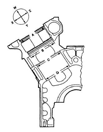
(3) Measure each cylinder bore at four locations as indicated by letters A, B, C, and D. Take two readings at
each location, 90 deg. to other as indicated by letters XZ and WY.
(4) The difference between the two readings at each level (out-of-round) must not exceed 0.0010 in. (0.030
mm).
NOTE
When measuring cylinder block bore, block should be flat on floor, main bearing caps installed and
tightened to a torque of 240 ft lb (325 Nm).
(5) Record the average of both readings taken at each level. These measurements must not exceed those
shown below. Taper between levels C and D must not exceed 0.0010 in. (0.030 in.)
Block
Maximum Allowable Average
Measurement at Location
A
B
C
D
New
5.3620 in.
5.3385 in.
5.2175 in.
5.2180 in.
136.195 mm
135.598 mm
132.525 mm
132.537 mm
Used
5.3635 in.
5.3395 in.
5.2185 in.
5.2185 in.
136.233 mm
135.623 mm
132.550 mm
132.550 mm
3-188
|