|
| |
TM 5-4210-220-34
3-8.
ENGINE - Continued
3-8.10
Crankshaft - Continued
NOTE
To
determine
journal-to-bearing
clearance, use the lowest dimensional
figure
obtained
from
the
journal
measurements and compare it with the
highest figure in the bearing table. All
measurements must be accurate to
nearest 0.0002 in. (.005 mm). The
bearing
clearances
can
also
be
measured using crushable plastic strip,
Use the 0.002 0.006 in. size to
determine the clearance. Always use
new bearing shells and tighten the
bearing caps (main journal to 260 ft lb
(350 Nm), connecting rod journal to 70 ft
lb (95 Nm).
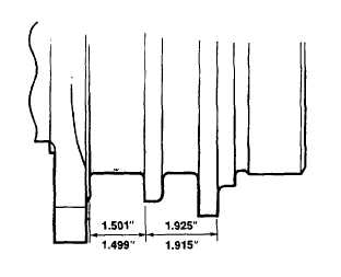
(15) Measure the crankshaft thrust washers
surfaces as shown.
(16) If
any
dimensions
are
outside
the
tolerances,
the
crankshaft
must
be
replaced.
(17) Inspect the crankshaft for cracks using any of the techniques detailed in para. 2-7. The two types of
indications to look for are circumferential fillet cracks in the critical areas shown or 45 deg. with the axis
cracks starting from either the critical fillet locations or the connecting rod journal holes.
(18) Replace the crankshaft if cracks of any nature are found.
INSTALLATION
(1) If a new crankshaft is to be installed, steam clean it with all oil plugs removed, to remove the rust
preventative.
WARNING
Death or serious injury could occur if compressed air is directed against the skin. Do not used
compressed air for cleaning or drying unless the pressure is/has been reduced to 30 psi (2.11 kg/cm2) or
less. When working with compressed air, always use chip guards, eye protection and other personal
protective equipment.
(2) Blow out all oil passages with compressed air and install the plugs.
(3) Install the crankshaft timing gear (12) on the crankshaft (10) as detailed in para. 3-8.7.
(4) Install the oil pump drive gear as detailed in para. 2-19.10.
(5) Install new slotted main bearing shells (16) in the block.
(6) Install new plain bearing shells (5) in the main bearing caps (18). Be sure the tang on the bearing fits into the
groove in the bearing cap.
3-178
|

