|
| |
TM 5-4210-220-34
3-8.
ENGINE - Continued
(5) To remove the sleeve, peen the outside diameter until the sleeve stretches sufficiently so it can be slipped off
the end of the crankshaft.
(6) To install a sleeve, stone the high spots from the contact surface. Coat the shaft with shellac or an equivalent
sealant and press the sleeve on the shaft using installer J21983 with guide studs J25002 and driver handle
J8092 as required. Then wipe off any excess sealant. An oversize seal must be used with a sleeve.
(7) Check the oil pump drive gear (8) and the crankshaft timing gear (12) for worn or chipped teeth. Replace as
required. For oil pump, see para. 2-19.10. For timing gear, see para. 3-8.7.
(8) Check the crankshaft thrust surface for excessive wear or grooving. If excessively worn, the crankshaft must
be replaced. Oversize thrust washers are available in sizes 0.005 in. (0.13 mm) and 0.010 in. (0.25 mm).
(9) If there is any sign of wear on the crankshaft, the crankshaft must be measured against specification. A worn
crankshaft must be replaced.
(10) Support the crankshaft on No. 1 and No. 4 main journals in V-blocks. Measure the total runout on journals
No. 2 and No. 3, the runout on each journal must be less than 0.002 in. (0.05 mm).
(11) If the high spots of runout on adjacent journals Is in the same or opposite directions, total runout must not
exceed 0.003 in. (0.08 mm). If the total runout on adjacent bearings is at right angles to each other, total
runout must not exceed 0.004 in. (0.10 mm).
(12) If runout specifications are exceeded, the crankshaft must be replaced.
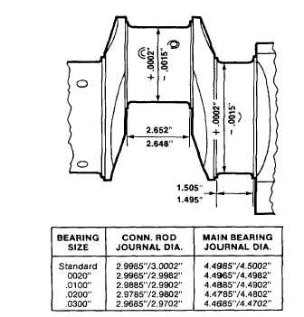
(13) Measure the main and connecting rod
journals
In
several
places
on
the
circumference so that taper, out-of-round,
and bearing clearances can be determined.
(14) The crankshaft must be replaced if:
• Any main bearing taper exceeds 0.0004
in. (0.010 mm).
• Any main bearing out-of-round exceeds
0.0005 in. (0.013 mm).
• Any connecting rod bearing taper
exceeds 0.0004 in. (0.010 mm).
• Any connecting rod bearing out-of-round
exceeds 0.0005 in. (0.013mm).Main
journal-to-bearing
clearance
exceeds
0.0055 in. (0.013 mm).
• Connecting rod journal-to-bearing
clearance exceeds 0.0045 in. mm).
3-177
|