|
| |
TM 5-4210-220-34
3-8.
ENGINE - Continued
3-8.8
Camshafts - Continued
(7)
Examine both faces of each camshaft end bearing and thrust washer. Also, check the thrust surface of the
camshaft gear for scoring or wearing. Thrust surfaces that are not damaged too severely can be smoothed
down with an oil stone. Thrust washer thickness should be 0.119 to 0.122 in. (3.02 to 3.10 mm).
(8)
Irspect the intermediate bearings, and the bushings in the front and rear camshaft end bearings. Replace the
bearings or bushings if they are worn excessively, or if the bushings In the end bearings have turned.
Bearing to shaft clearance, front and rear, should be 0.0025 to 0.0040 in. (0.064 to 0.102 mm). The
absolute limit is 0.0060 in. (0.152 mm). The intermediate bearing to shaft clearance should be 0.0025 to
0.0050 in. (0.064 to 0.127 mm), with a limit at (0.0090 in. (O 229 mm).
NOTE
Rear camshaft and bearings are available in 0.010 in. (0.254 mm) or 0.020 in. (0.51 mm) undersize for use
with worn shafts which exceed the specified clearance limits. New bushings must be finish bored to a 20
rms finish after installation and checked for the proper press fit, which is Indicated if the bushings will not
move when a 2000 lb (910 kg) end load is applied. Also, the inside diameter of the bushings must be
square with the rear face of the bearing within 0.0015 in. (0.038 mm) total indicator reading, and concentric
with the outside diameter of the bearing housing within 0.002 in. (0.05 mm) total indicator reading. The
bushings must project 0.045 In. 0.055 in. (1.14 to 1.40 mm) from each end of the rear camshaft end
bearings. The bushings in the front camshaft end bearings must be flush with the ends of the bushing bore.
(9)
Examine the intermediate bearing lock screws and the cylinder block tapped holes for damaged or stripped
threads.
(10)
Replace the seal In the left bank camshaft front end bearing. Also, examine the spacer used at the front end
of each camshaft. The outside diameter of the spacer used in the left bank front end bearing must provide a
smooth oil seal contact surface. The outside diameter Is not ground and polished on the original spacer used
on the right bank camshaft. Only the polished spacer is available for service and may be used in either
position.
(11)
Examine the teeth on the water pump drive gear and the camshaft gears for wear, pitting or scoring. Also
check the key ways, and all the threaded holes in the gears and camshaft pulley for stripped or damaged
threads.
(12)
Repair all parts showing signs of damage, and replace parts that can not be repaired
ASSEMBLY
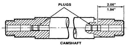
(1)
Press new plugs into each end of each camshaft as shown.
3-158
|