|
| |
TM 5-4210-220-34
3-8.
ENGINE - Continued
NOTE
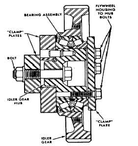
Prior to the installation of the idler gear assembly, bearing pre-load must be checked. Carry out steps 15 thru 26 to check
idler gear bearing pre-load.
(15)
Lubricate the idler gear bearings using engine oil (item 17, Appendix B) prior to pre-load testing.
(16)
Attach the two 3/4 in. bearing test fixture plates (11, Appendix D) to the Idler gear hub using a 1/2 in - 13 bolt,
washers and nut. Tighten the nut to 90 ft lb (122 Nm).
(17)
Attach the 3/8 in. bearing test fixture plate
(11, Appendix D) to idler gear hub using 3/8
in. - 16 capscrews. Tighten the capscrews
to 40 ft lb (54 Nm).
(18)
Clamp the idler gear assembly and fixture in
a vise.
(19)
Tie one end of a piece of lintless 1/8 in.
cord around a 1/8 in. round piece of wood.
Place the wood between two of the gear
teeth and rap the cord around the periphery
of the gear several times. Attach the other
end of the cord to a spring scale J8129.
(20)
Maintain a straight steady pull on the cord
and scale, 90 deg. to the axis of the hub,
and note the pull, in pounds and ounces,
required to start the gear rotating, Make
several checks to obtain an average
reading.
(21)
If the pull is within 1/2 lb minimum to 4 lbs maximum, and does not fluctuate more than 2 lb 11 oz., the idler
gear and bearing assembly is satisfactory for use. If the scale reading is within the 1/2 to 4 lb specified, but
fluctuates more than 2 lb 11 ounces, the idler gear and bearing assembly must NOT be installed on the
engine.
(22)
Fluctuations in scale reading may be caused by the cones not being concentric to each other, damaged
cones or rollers, or dirt or foreign material within the bearings. In these cases, the bearing should be
inspected for the cause of fluctuation in the scale readings and corrected or a new bearing installed.
(23)
A scale reading which exceeds the specified maximum indicates binding of the bearing rollers, or rollers
improperly installed.
(24)
When the scale reading is less than the specified minimum, the bearing is more likely worn and the bearing
should be replaced.
(25)
After the pre-load check is completed, remove the bearing test fixture plates (11, Appendix D) from the idler
gear assembly.
(26)
Attach the bearing retainer (2) to the Idler gear (3) using new capscrews (1). Tighten the capscrews to 29 ft
lb (39 Nm).
(27)
Attach the idler gear assembly as detailed in the INSTALLATION section preceding.
3-153
|