|
| |
TM 5-4210-220-34
3-8.
ENGINE - Continued
(9)
Tighten capscrews progressively in steps to the final torque and sequence as shown in the sequence shown
on the illustration.
(10)
Check whether the crankshaft is fitted with a sleeve.
(11)
If no sleeve is installed, place oil seal expander J4239 against the end of the crankshaft using handle J8092
and guide studs J25002.
(12)
If a sleeve is installed, place oil seal expander J8682 against the end of the crankshaft. An oversize oil seal
must be used.
(13)
Liberally lubricate the seal (standard or oversize), the crankshaft and the crankshaft oil seal expander with
engine oil. (item 17, Appendix B). Failure to adequately lubricate these areas during seal installation can
result In seal lip damage at engine start-up.
NOTE
Keep the sealing lip clean and free from scratches.
In addition, a plastic coating which acts as a
sealant is applied to the outer surface of the seal
case. Do not remove this coating.
(14)
With the lip of the seal pointed toward the
engine, slide the seal over the expander
and onto the crankshaft. Remove the
seal
expander
and
guide
studs,
as
required.
(15)
Install crankshaft rear oil seal installer
J21112-2 and guide studs J9727-5. Using
handle J3154-1, drive the seal in place until
the installer seats squarely on the butt of
the crankshaft. Remove the seal installer
and guide studs.
(16)
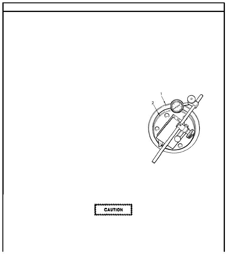
Check the squareness of the seal (1) in relation to the face of the crankshaft butt (2) by attaching a magnetic
base dial indicator to the rear butt of the crankshaft as shown.
(17)
Pry the crankshaft to the rear end of the block and position the point of the dial indicator on the seal face.
Rotate the crankshaft and note the seal face readings at the 12, 9, 6, and 3 o’clock positions. The total run-
out at each position should not exceed 0.015 in. (0.381 mm).
The hex head of the front crankshaft bolt may be used to turn the crankshaft. However the barring operation should
ALWAYS be performed in a clockwise direction. It is very important to ensure the bolt is not loosened. Serious
engine damage may result if the pulley is not securely fastened to the crankshaft.
(18)
If any reading is over 0.015 in. (0.381 mm) place the seal installer J21112-2 over the seal and lightly tap with
a soft-faced hammer at the high points This will ensure that the tool is squarely seated on the butt of the
crankshaft.
3-139
|