|
| |
TM 5-4210-220-34
3-7.
TRANSMISSION-Continued
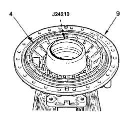
(22)
Using inner seal protector J24210,
carefully install the piston (4) into the
rear cover (9). Use extreme care to
prevent the lip of either seal folding back
over itself. If installation is difficult,
remove the piston and check the seal
and cover bore before again attempting
installation.
(23)
Remove the seal protector. Install thirty springs (3). Install the spring retainer (2), cupped side first, onto
the springs.
(24)
Using compressor components J24204-1 and J24204-2, compress the retainer and springs. Install snap
ring (1), and remove the compressor.
(25)
If the orifice plug (13) was removed from the output shaft, install a new plug, orificed side first. Use
installer J24369 to properly position the plug in the shaft. The plug must clear the chamfer at the front of
the plug bore in the output shaft.
(26)
If the bushing (14) was removed from the front of the output shaft, install a new bushing with installer
J24769 located 0.330-0.350 in. (8.38-8.89 mm) from front of shaft.
(27)
Press speedometer drive gear (26), spacer sleeve (27) and bearing (29) onto output shaft. Install
assembled shaft.
(28)
Install proper snap ring to match groove in the housing. Be sure snap ring is expanded fully into the
groove.
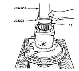
(29)
Install oil seal (30) , spring-loaded lip
first. Use installerJ24202-1A and driver
handle J24202-4 to locate the rear of the
seal (30) 0.60-0.70 in. (15.2-17.8 mm) in
front of the rear mounting surface.
3-63
|