|
| |
TM 5-4210-220-34
2-9.
SIREN AND PA SYSTEM - Continued
(3)
When Q301 and Q302 are replaced, be
sure to adjust the symmetry of the output
waveform before returning the module to
use. To do this, connect a 5.5 ohm, 200
watt dummy load across pins (5 and 6) of
P301 in place of the speakers. Connect an
oscilloscope across the dummy load and
activate the Yelp signal. Adjust R158 on
the main circuit board to obtain the best
possible square wave.
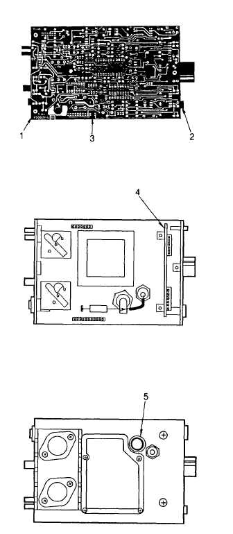
1.
Self Tapping Screw, No. 8 X 1/2 in.
2.
Knob
3.
Main Circuit Board
4.
Front Circuit Board
5.
Fuse Holder 342002
R301 Potentiometer, 10K Ohm
C301 Capacitor, 500 uF, 15 V,
electrolytic
C302 Capacitor, .001 uF, 100 V, Disc
C303 Capacitor, .001 uF, 100 V, Disc
C304 Capacitor, .005 uF, 100 V, Disc
C305 Capacitor, .005 uF, 100 V, Disc
Q301 Transistor, NPN, Silicone
2N5885
Q302 Transistor, NPN, Silicone
2N5885
T301 Output Transformer
SW302 Slide Switch
F301 Fuse, 20 amp, 3AG
P301 Connector 8-pin
J302 Connector, 12-pin
J303 PCB Connector
(4) To remove the main circuit board remove
the three screws that hold the board in the
siren module. Disconnect the socket at the
rear of the board and lift the board out of
the module. When replacing the main
circuit board, aline the socket at the rear so
that the color dot on the socket is adjacent
to the color dot on the circuit board. Also
be sure that the two plugs on the front of
the circuit board mate properly with sockets
on the front circuit board.
(5) To remove the front circuit board, remove
the main circuit board as described above.
Loosen control knob set screws and slide
the
knobs
from
their
control
shafts.
Remove the spanner nuts that hold the
SELECTOR and the GAIN control to the
front panel of the module. Remove the
screw that holds the siren button bracket in
place and lift out the circuit board.
(6) To test the main circuit board, the following
tables list voltages and waveforms that
appear on the integrated circuits and
transistors when the SELECTOR switch is
set to its various positions
2-27
|