|
| |
TM 5-4210-220-34
2-9.
SIREN AND PA SYSTEM.
This task covers:
a.
Removal
b. Installation
c. Repair
INITIAL SETUP:
TOOLS
EQUIPMENT CONDITION
Shop Equipment, Automotive
Main Engine Shutdown (see TM 5-4210-220-12)
Maintenance and Repair,
APU Engine Shutdown (see TM 5-4210-220-12)
NSN 4910-00-754-0650
Batteries Disconnected (see TM 5-4210-220-12)
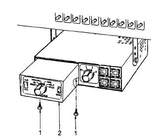
REMOVAL
Remove screws (1) and pull siren module (2) out of
chassis.
INSTALLATION
(1) Check that plugs on the back side of siren
module and corresponding receptacles in
chassis are securely installed. Secure
attachment is necessary to ensure proper
electrical contact when module is installed.
(2) Slide module (2) into place In chassis.
Install and tighten screws (1).
REPAIR
Siren Module Repair
NOTE
Repair of the siren unit or module Is only done by electronic maintenance personnel at the intermediate
level. The following repair procedure is limited to cover the siren module only as no functions are
identified for the option control module .
(1) Only a limited number of components are replaceable in the siren module since components on the
printed circuit boards are not considered individually replaceable. Use the illustrations and legends to
identify the replaceable parts. For convenience, the parts are Identified by their circuit reference
numbers.
Be careful when replacing and soldering small components. Heat easily damages integrated circuits,
transistors, capacitors and circuit boards. Therefore, it is advisable to use long nose pliers or similar
devices as a heat sink on component leads being soldered.
(2) When replacing the output amplifier transistors, Q301 and 0302, always ensure that they are replaced in a
matched pair. Make sure that the wire insulators used with the transistors are replaced also. When installing
new transistors use a heat sink compound on both sides of the mica insulators. Be sure the insulators are
installed correctly, otherwise a short circuit may occur.
2-26
|