|
| |
TM 5-4210-220-34
3-7.
TRANSMISSION - Continued
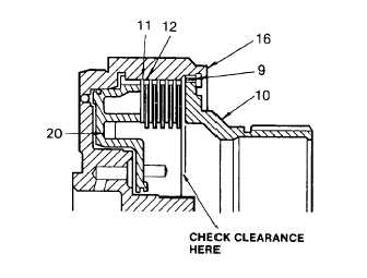
(33) Before completing the assembly, the clutch clearance must be established. Install forward piston (20) into
clutch housing (16).
(34) Beginning with an external-tanged plate, alternately install five external-tanged plates (11 ) and five internal-
splined plates (12) into forward-clutch housing (16).
WARNING
Do not install forward-clutch hub and
fourth-clutch driving hub into the fourth-
clutch housing assembly. Be sure the
forward-clutch hub and the fourth-clutch
driving hub are Installed into the forward-
clutch assembly. If these two hubs are
installed into the fourth-clutch housing
assembly by mistake, the transmission
will operate in reverse when the driver
selects any forward range.
(35) Install the fourth-clutch driving hub (10) into
housing (16) and retain it with snap ring (9).
(36) While holding hub (10) firmly against snap
ring (9), measure the clutch clearance with
gage J24192 at the location shown. When
clearance are satisfactory, the thinner step
of the gage
will enter between the driving hub and clutch plates; the thicker step will not. The prescribed clearance is
0.080 - 0.120 in. (2.03 - 3.05 mm).
(37) If the clutch clearance is not within the specified limits, remove snap ring (9), fourth-clutch driving hub (10)
and clutch plates (11) and (12). Replace clutch plates, as required, to obtain the desired clearance. Refer to
wear limits (Appendix C) to determine the plate thicknesses.
(38) When the clutch clearance is within the
specified limits of 0.080 0.120 (2.03 3.05
mm), remove snap ring (9) and hub (10),
clutch plates (11 and 12), and piston (20).
(39) Place piston on a work table with the return
spring
bosses
up.
Lubricate
with
transmission fluid (item 9, Appendix B) and
install two new lip-type teflon seal rings into
the inner and outer seal ring grooves in the
piston.
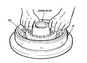
(40) Install seal ring protector J24216-01 onto
the clutch housing hub (4).
(41) Lubricate the piston seal rings with
transmission fluid (item 9, Appendix B) and centrally locate the piston (19) in the housing bore. Place the
piston and piston housing under an arbor press and apply pressure evenly until the piston is properly seated.
(42) f a press is not available, seat the piston in the housing bore by tapping the piston lightly with a mallet in a
continuous circular pattern until the piston is properly seated.
3-42
|


