|
| |
TM 5-4210-220-34
3-7.
TRANSMISSION - Continued
(28) Install PTO gear in oven or oil bath and heat
to 350 - 375 deg. F (177 - 191 deg. C).
(29) Carefully install the PTO gear onto the
forward clutch housing (chamfer end first),
until the snap ring expands into the PTO
gear groove. Make sure the snap ring is
expanded and free in the internal groove of
the gear before the gear cools. Failure to
obtain this condition can result in difficulty
during subsequent removal.
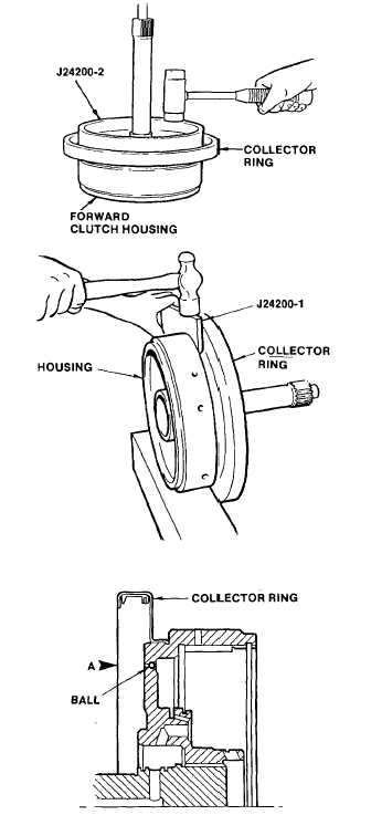
(30) Position the forward clutch housing, turbine
shaft upward. Apply retaining compound
(item 23, Appendix B) onto the collar of the
collector ring. Install the collector ring. Use
installer J24200-2 to drive the collector ring
onto the clutch housing. Use light hammer
blows, and work around the entire installer
circumference.
(31) Using staking tool J24200-1, bend the edge
of the collector ring into the groove in the
clutch housing. Press to shoulder and
bend metal into groove for entire
circumference.
(32) Check the four steel balls (7) in the housing.
Make sure they are securely staked in the
housing and are free to move without
restriction. Must withstand 30 lb (133.45 N)
load applied in direction indicated by arrow
A.
3-41
|

