|
| |
TM 5-4210-220-34
3-7.
TRANSMISSION - Continued
NOTE
Valves, when installed dry, should move by their own weight,
(4) Install trimmer plug (7).
(5) Install springs (4 and 5), valve stop (6), and retainer plug (2).
(6) Compress springs (4 and 5) and install retainer pin (3) to secure plug (2).
n.
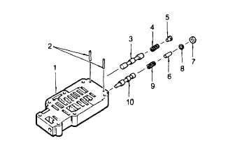
Low Shift Valve Inspection, Repair And Assembly
(1) Depress valve stop (5) against its spring
and remove retainer pin (2).
(2) Release spring pressure and remove valve
stop (5), spring (4) and relay valve (3).
NOTE
Note position of adjusting ring (7) in
relation
to
retainer
pin
(2)
before
removal.
(3)
Depress adjusting ring (7) against its spring
and remove retainer pin (2).
(4) Remove adjusting ring (7), washer (8), valve stop (6), spring (9), and valve (10).
WARNING
Dry cleaning solvent P-D-680 (safety or Stoddard’s solvent) is potentially dangerous. Avoid repeated and
prolonged breathing of vapors and skin contact with the liquid. Do not use near open flame, arcing
equipment or other ignition sources. Always wear eye protection and protective clothing. The flash point
of P-D-680 is 100 to 138 deg. F (30 to 59 deg. C).
(5) Inspect and clean parts with dry cleaning solvent (item 10, Appendix B). Replace any damaged parts.
NOTE
Valves, when installed dry, should move by their own weight.
(6) Install valve (10) into valve body (1).
(7) Install spring (9), valve stop (6), washer (8), and adjusting ring (7). Aline the hole in valve stop (6) with the pin
hole in valve body (1). Position the adjusting ring in the same position as it was before removal.
(8) Press inward against adjusting ring (7) until retainer pin (2) can be installed.
3-23
|