|
| |
TM 5-4210-220-34
3-7.
TRANSMISSION - Continued
NOTE
If bearing (1) shows signs of excessive wear or damage, it must be replaced.
(4)
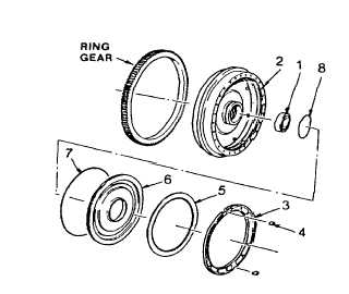
Install seal ring (8) onto the flywheel hub, and seal ring (7) onto the outside diameter of lockup clutch piston
(6). Lubricate both seal rings with petroleum jelly (item 21, Appendix B).
(5)
Place a pencil mark on the edge of the
lockup clutch piston opposite a dowel pin
hole. Also place a pencil mark in the
flywheel bore, opposite a dowel pin.
(6)
Install the lockup clutch piston into the
flywheel, alining the pencil marks, to
engage the recesses in the piston with the
dowel pin. Be certain the dowel pins are
engaged.
(7)
Install the lock keys (4) in the lock key
grooves of the flywheel. Use petroleum
jelly (item 21, Appendix B) to retain them.
(8)
Install the lockup clutch plate (5).
(9)
Install the lockup clutch backplate (3) flat side first, engaging the notches in the plate with the keys (4) in the
flywheel.
(10) Carefully center the lockup clutch plate in the flywheel. Install the torque converter turbine (9), engaging its
hub splines with the internal splines of the lockup clutch plate.
(11) Flywheel, lockup clutch, and turbine are now assembled and ready for final installation.
f.
Disassembly And Repair Of Torque Converter Stator Assembly
(1)
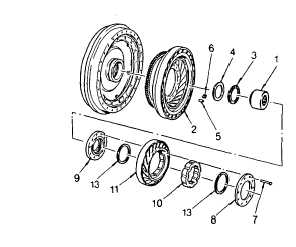
Rotate stator freewheel roller race (1) in a
clockwise direction to free it for removal
from the stator (2).
(2)
Remove race (1), thrust bearing (3), thrust
bearing race (4), ten stator rollers (5), and
ten freewheel roller springs (6) from stator
assembly (2).
NOTE
Do not disassemble the stator assembly
unless replacement of stator thrust
washer (9), rivets (7), or washer (8) is
necessary. If stator (11) or cam (10) is
cracked
or
damaged,
replace
the
complete stator assembly.
A hydraulic press having a minimum capacity of five tons, an adjustable table, and a pressure gage, to assist in
determining the rivet staking load, is required to rebuild the stator assembly.
3-15
|