|
| |
TM 5-4210-220-34
3-7.
TRANSMISSION - Continued
(13) Inspect the rivet holes for burrs or swelling. Deburr as necessary.
(14) Inspect lockup clutch drive gear for cracks distortion, abrasion, battered or broken teeth.
(15) Reassemble components, being sure to correctly index punch marks of the lockup drive gear, turbine, and
hub. Use the new rivets to help index the components.
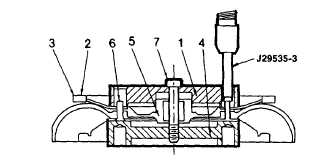
(16) Install sixteen new rivets (6) through the turbine (3), turbine hub (5), and lockup clutch gear (2).
(17) Assemble base plate J29535-1 (4) placing
solid side of plate against the rivet heads.
(18) Place guide plate J29535-2 (1) on top of the
assembled components. Centrally locate
the rivets in the holes of the guide plate.
(19) Retain the turbine assembly and the two plates with bolt (7). Tighten the bolt to 50 ft lb (68 Nm).
(20) Place the turbine and fixture in hydraulic press.
(21) Insert staking tool J29535-3 into the top plate. Using an alternating pattern, swage each rivet.
(22) Remove staking tool, retaining bolt, guide, and base plate.
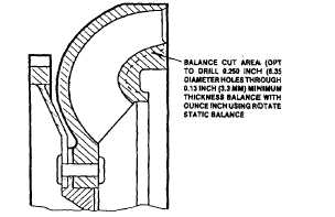
(23) Each
reclaimed
assembly
must
be
balanced by rotating type static balance to
within 1.0 ounce in. (720 Nm) by removing
metal from area indicated but maintaining
0.13 in. (3.30 mm) minimum wall. It is also
possible to drill 0.250 in. (6.35 mm)
diameter holes for balancing.
e.
Assembly Of Lockup Clutch, Flywheel And Turbine Assembly
(1)
If the starter ring gear was removed, install a new gear, as follows.
(2)
Install the starter ring gear after heating it uniformly to 400 deg. F (204 deg. C) maximum temperature. Be
sure the chamfers of the teeth are facing to front of flywheel, engine side for proper starter pinion
engagement. The ring gear must seat firmly against the shoulder on the flywheel.
(3)
Place flywheel on assembly table, with the cavity side upward.
3-14
|


