|
| |
TM 5-4210-220-34
2-21.
FRONT AXLE - Continued
2-21.2
Differential Carrier - Continued
(3)
At teeth side of ring gear, tighten adjustor
until it contacts the bearing cup. Continue
tightening adjustor two or three notches and
this will preload bearings and provide
backlash.
(4)
Measure backlash with a dial indicator.
Used
Gear
Ring
Reset
to
backlash
recorded before disassembly. New Gear
Ring Backlash should be 0.006 0.016 in.
(0.15 0.41 mm). If backlash is incorrect,
proceed as described below to readjust.
(5)
To add backlash: Loosen the adjustor on
the teeth side of the ring gear several
notches. Loosen the opposite adjustor one
notch. See illustration for definition. Return
to adjustor on teeth side of the ring gear
and tighten adjustor until it contacts the
bearing cup. Continue tightening the same
adjustor 2 or 3 notches. Recheck backlash.
(6)
To remove backlash: Loosen the adjustor
on the teeth side of the ring gear several
notches. Tighten the opposite adjustor one
notch. Return to adjustor on teeth side of
ring gear and tighten adjustor until it
contacts the bearing cup. Continue
tightening the same adjustor 2 or 3
notches. Recheck backlash.
b.
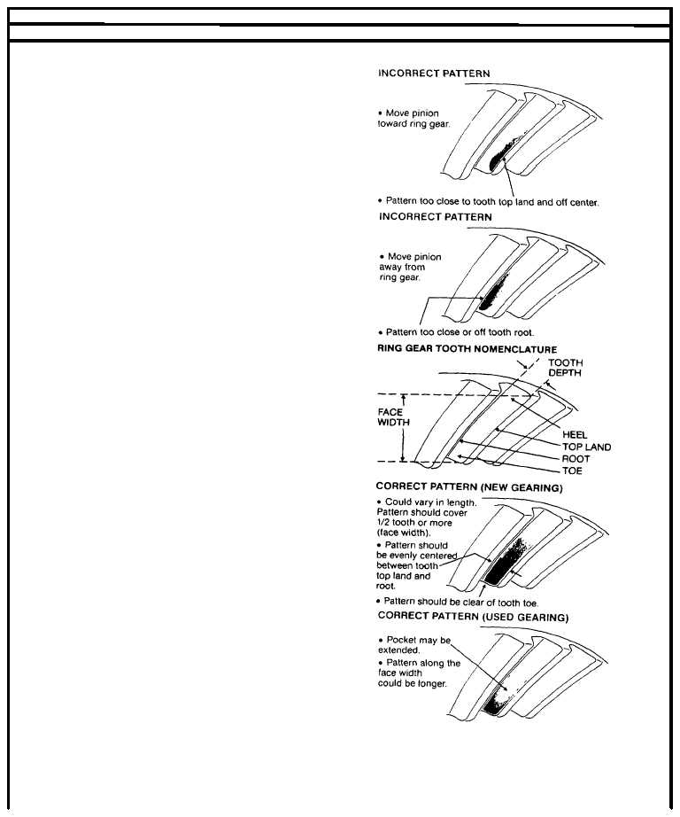
Ring Gear And Pinion Tooth Contact Adjustment
(1)
Check tooth contact pattern (new gear).
Paint twelve ring gear teeth with marking
compound and roll the gear to obtain a
contact pattern. The correct pattern is well-
centered on the ring gear tooth within
lengthwise contact clear of the toe. The
length of the pattern in an unloaded
condition is approximately one-half to two-
thirds of the ring gear tooth. If adjustment
Is necessary proceed to step 3.
(2)
Check tooth contact pattern (used gear).
Used gearing will not usually display the
square, even contact pattern found in new
gear sets. The gear will normally have a
"pocket" at the toe-end of the gear tooth
which tails into a contact line along the root
of tooth. The more use a gear has had, the
more the line becomes the dominant
characteristic of the pattern. Adjust used
gear sets to display the same contact
pattern observed before disassembly. A
correct pattern is clear of the toe and
centers evenly along the face width
between the top land and root. Otherwise, the length and shape of the pattern are highly variable and is considered
acceptable as long as it does not run off the tooth at any point.
2-298
|