|
| |
TM 5-4210-220-34
2-21.
FRONT AXLE - Continued
NOTE
Carry out step 3 even if bearing (48) only
needs replacement.
(3)
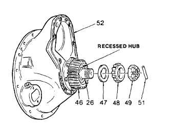
Remove bearing cone (48), spacer (47),
and gear (46) in one operation using a
suitable puller as shown.
(4)
Install gear (46) on pinion (26). Be sure
recessed hub is facing out as shown.
(5)
Install spacer (47) and bearing (48). Use a
hammer and a suitable sleeve to seat
bearing.
(6)
Install castle nut (49) and tighten to 840 ft lb
(1140 Nm). Continue to tighten nut further
until a roll pin hole in pinion alines with a
slot in castle nut.
(7)
Install roll pin (51).
(8)
Proceed with installation of power divider as
detailed in para. 2-20.1.
ADJUSTMENT
NOTE
Bearing preload adjustment Is performed for both pinion and differential bearings. It maintains proper
gear alinement by creating correct bearing cone and cup relationship for free rotation under load. The
pinion pilot bearing does not require a preload adjustment.
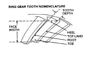
Ring gear tooth contact adjustment positions ring gear and pinion for best contact under load Correct
adjustment distributes torque evenly over gear teeth and helps maximize gear set life.
a.
Differential Bearing Preload And Ring Gear Backlash Adjustment
(1)
Loosen the bearing adjustor on the same
side as, the ring gear teeth until its first
thread is visible.
(2)
Tighten
the
bearing
adjustor
on
the
backface side of the ring gear until there is
no backlash. This can be tested by facing
the ring gear away from the body while
gently rocking the gear from side to side.
There should be no free movement. Rotate
the ring gear and check for any point where
the gear may bind. If such a point exists,
loosen and retighten the back side adjustor.
Make all further adjustments from the point
of tightest mesh.
2-297
|