|
| |
TM 5-4210-220-34
2-19.
ENGINE - Continued
2-19.12
Throttle, Fuel Shutdown, And Fire Pump Governor - Continued
c.
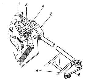
Pump Governor Adjustment.
NOTE
Mechanical Governor, fuel shutdown and foot throttle chamber must be adjusted and the engine idle and maximum
rpm must be set prior to carrying out pump governor adjust.
(1)
Be sure pump governor has been installed as in REPLACEMENT following. This procedure ensures the
assembly itself is adjusted correctly.
(2)
With
engine
shutdown,
rotate
pump
governor arm (3) counterclockwise until the
pivot bolt is against the outer end of the slot
of the pump governor link (4).
(3)
Be sure bracket (5) on pump governor shaft
is held to the left near bracket (A) and then
tighten locking nut and bolt (1 and 2) on the
pump governor arm.
(4)
Start main engine and start fire pump in
structural mode. Be sure pump is flooded.
Using hand throttle on structural control
panel adjust engine speed so that pump
pressure increases to 150 psi (1034 kPa).
Be sure pump pressure is stable. Open
various
discharges
and
check
pump
pressure restabilizes to this pressure. Shut
pump down.
(5)
Set pump to CFR mode and start pump. Switch on governor and check pump pressure increase to 250 psi
(1720 kPa). If pressure exceeds 280 psi (1930 kPa) switch off pump governor immediately. Reduce
pressure as detailed in following steps.
(6)
With pump pressure stabilized, adjust pressure to 250 psi (1720 kPa) using air control valve mounted on
service brake plate.
(7)
Open bumper turret and roof turret in turn and check pressure restabilizes to 250 psi (1720 kPa) after each
operation.
REPLACEMENT
a.
Fuel Shutdown Replacement
NOTE
If a new engine is being prepared for installation carry out all instructions.
If the fuel shutdown is being removed and installed on engine(s) already in service start at instruction 3.
2-242
|