|
| |
TM 5-4210-220-34
2-19.
ENGINE - Continued
(5)
Be sure that ’when electrical connection is made, air is exhausted from the solenoid and the plunger retracts.
(6)
Be sure that when 12-Vdc supply is removed, the plunger extends. Replace whole assembly if plunger fails.
See REPLACEMENT following.
(7)
Reconnect electrical supply to place solenoid in engine run position, cylinder retracted.
(8)
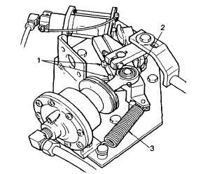
Install arm (2) and aline it with the plunger ensuring it rests against the plunger. Tighten screw (1) firmly.
(9)
Disconnect electrical supply, and check all fuel injectors are in the no-fuel position (injector control rack fully
withdrawn).
(10)
Adjust arm (2) as required. The Injector racks must be fully withdrawn and checked to go to that position
whenever the engine ignition is set to OFF.
b.
Foot Throttle Chamber Adjustment
NOTE
Engine must be shutdown.
Exhaust valve clearance, injector timing, mechanical governor and injector control racks must be set before
adjusting the throttle.
(1)
Ensure air tanks are pressurized. If no air,
pressurize using shop connection on left
side of pump body. Check all air tanks are
at 100 psi (690 kPa).
(2)
Check screws (1) and nuts (2) on throttle
arm are loose.
(3)
Press and release foot throttle in cab a few
times and ensure throttle chamber rod
moves
freely.
Check
spring
(3)
is
connected and pulls throttle arm promptly
back when throttle pedal is released.
(4)
With engine shut down, release foot throttle
in cab.
(5)
Tighten clamp screws (1) and nuts (2).
(6)
Depress foot throttle up and down a few times to check operation of the foot throttle and the governor speed
shaft.
(7)
With the foot throttle depressed, and the rocker covers removed, see para. 2-19.3, check that fuel injectors
are in the full-fuel position (injector control rack fully in).
2-241
|