|
| |
TM 5-4210-220-34
2-19.
ENGINE - Continued
2-19.9
Water Pump - Continued
(31)
Clean parts with compressed air.
(32)
Place the adhesive washer in the impeller bond area with the ceramic insert on top.
(33)
Clamp ceramic insert and impeller together with 3/8 in. bolt, nut and two flat washers. Tighten to 10 ft lb (14
Nm).
(34)
Place impeller assembly in level position, insert upwards, in an oven preheated to 350 deg. F (177 deg. C)
for one hour to cure adhesive.
(35)
Cool impeller to room temperature.
(36)
Make sure mating surfaces of water seal and the ceramic insert in impeller are free of dirt or oil film.
(37)
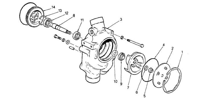
Apply small amount of anti-seize compound (item 4, Appendix B) to the threads of the pump shaft (8).
(38)
Place impeller (7), washer (6), and new locknut (5) on shaft.
(39)
Hold the pump gear securely in a brass jawed vise. Draw impeller down on tapered shaft with locknut.
Tighten nut to 40 ft lb (54 Nm).
(40)
Scribe a line across impeller, nut, and shaft.
(41)
Scribe a line across water pump, gear, and shaft.
(42)
Using adapter J33765 inserted into impeller puller holes, apply a torque of 80 ft lb (108 Nm) to the impeller.
2-226
|

