|
| |
TM 5-4210-220-34
2-19.
ENGINE - Continued
2-19.7
Exhaust Valves - Continued
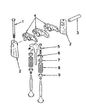
(21) Swing the rocker arm assembly into position making
sure the valve bridges are properly positioned on
the rear valve stems. This precaution is
necessary to prevent valve damage due to
mislocated valve bridges.
(22) Install the rocker arm shaft brackets (2) and shaft
(3).
(23) Install the two bolts (1) holding the brackets to the
cylinder head and tighten to 100 ft lb (136 Nm).
(24) Install the fuel pipes between the injectors and fuel
connectors. Be sure all shipping caps are removed
prior to installation.
(25) Fill the cooling system.
(26) Check the exhaust valve clearance as detailed in
ADJUSTMENT preceding.
REPAIR
a.
Exhaust Valve Guide Repair
NOTE
The valve guides cannot be repaired; if the valve stem to guide clearance is excessive, replace the valve
guide as detailed following.
(1) Pull out the valve guide oil seal and discard.
(2) Support the cylinder head, bottom side up, on 2 in. (50 mm) thick wood blocks.
(3) Using tool J6569 and a hammer, drive the valve guide out from the cylinder head.
(4) Place the cylinder head right side up on an arbor press.
(5) Install the internally threaded end of the valve guide in the installing tool J21520.
(6) Position the guide squarely in the bore in the cylinder head and press the tool J21520 gently to start the
guide.
(7) Press the guide in until the tool contacts the cylinder head. The tool installs the guide 0.670 - 0.710 in. (17 -
18 mm) above the top of the cylinder head.
2- 210
|