|
| |
TM 5-4210-220-34
2-19.
ENGINE - Continued
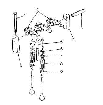
(7) Thread the valve spring compressor J7455 into one of the rocker shaft bolt holes in the cylinder head.
Compress the valve spring only sufficiently to install the locks. Excessive compression could damage
stem oil seals (10).
(8) Apply pressure to the tool arm to compress the spring. Install the two-piece taper valve lock (6).
(9) Give the end of the valve stem a sharp tap with a plastic hammer to seat the locks.
(10) Using spring checking gage J25076-B, note the gage reading the moment the exhaust valve starts to open.
The minimum pressure must not be less than 20 lb (9.1 kg).
(11) Repeat for all valves.
(12) When complete install the injector rocker
arms, and push rods. Install the cylinder
head on the engine as detailed in para. 2-
19.8.
(13) Place the valve bridge (5) in a vise and
loosen the locknut on the bridge adjusting
screw.
(14) Install the valve bridge on the valve bridge
guide (11).
(15) While firmly pressing straight down on the
pallet surface of the valve bridge, turn the
adjusting screw clockwise until it just
touches the valve stem.
(16) Turn the screw an additional 1/8 to 1/4 turn
clockwise
and
tighten
the
locknut
fingertight.
To avoid bending the bridge guide or rear valve stem, never loosen or tighten the locknut with the bridge on the
engine.
(17) Remove the valve bridge, install in a vise and while holding the screw tighten the locknut to 25 ft lb (34 Nm).
(18) Lubricate the valve bridge and guide with engine oil (item 17, Appendix B) and install bridge on the guide.
(19) Place a 0.0015 in. (0.038 mm) (feeler gage under each end of the valve bridge. While pressing down firmly
on the pallet surface, both feeler gages must be tight. If not tight, readjust screw.
(20) Adjust all bridges similarly.
2-209
|