Order this information in Print

Order this information on CD-ROM

Download in PDF Format


Click here to make tpub.com your Home Page

Page Title: ADJUSTMENT (cont)
Back | Up | Next

Click here for a printable version

Google


Web
www.tpub.com

Home


Information Categories
.... Administration
Advancement
Aerographer
Automotive
Aviation
Combat
Construction
Diving
Draftsman
Engineering
Electronics
Food and Cooking
Math
Medical
Music
Nuclear Fundamentals
Photography
Religion
USMC
   
Products
  Educational CD-ROM's
Printed Manuals
Downloadable Books


TM 5-4210-220-34 2-19. ENGINE - Continued 2-19.6 Injector Controls - Continued 
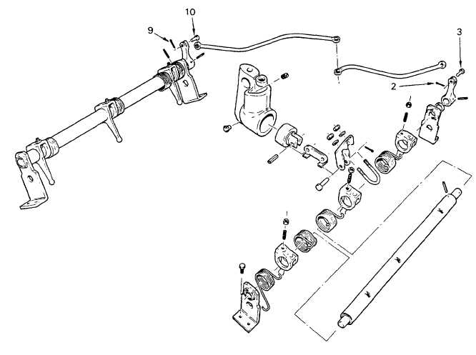
(14)  Remove spring pin (2) and clevis pin (3) from right hand fuel rod and injector control tube lever. (15)  Hold the left hand injector control tube lever in the full-fuel position and adjust all left-hand control rack levers as In steps 8 and 9. (16)  Repeat step 15 for the right hand control rack levers, setting these against No.  1R. (17)  When  all are adjusted, check each one is free to move as detailed in step 9. (18)  Insert clevis pins (3 and 10) into the fuel rod and injector control tube levers and install split pins (2 and 9) 2-196

Privacy Statement - Press Release - Copyright Information. - Contact Us - Support Integrated Publishing

Integrated Publishing, Inc. - A (SDVOSB) Service Disabled Veteran Owned Small Business