|
| |
TM 5-4210-220-34
2-19.
ENGINE - Continued
2-19.6
Injector Controls.
This task covers:
a.
Adjustment
b.
Removal
c.
Installation
d.
Repair
TOOLS
Both Engine Covers Removed
Shop Equipment, Automotive
(see TM 5-4210-220-12)
Maintenance and Repair,
Both Rocker Covers Removed (see para. 2-19.3)
NSN 4910-00-754-0705
J23190 Injector Rack Gage
MATERIALS/PARTS
J25560 Injector Rack Gage
17, Appendix B Engine Oil
J25558 Throttle Delay Pin Gage
5149510 Rocker Cover Gasket
EQUIPMENT CONDITION
Main Engine Shutdown (see TM 5-4210-220-12)
APU Shutdown (TM 5-4210-220-12)
Batteries Disconnected (see TM 5-4210-220-12)
ADJUSTMENT
Before adjusting injector controls, be sure exhaust valves have
correct clearance, injectors have been timed, and governor gap
has been set up.
(1) Disconnect foot throttle and pump governor from
main engine governor as detailed in para. 2-19.12.
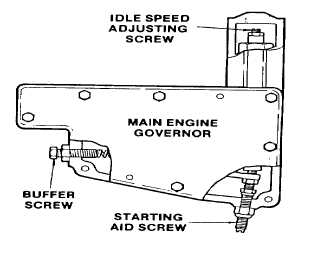
(2) Turn the governor idle speed adjusting screw (1)
until 1/2 In. (13 mm) of threads project from the
locknut when the nut is against the high speed
plunger.
(3) Back out the buffer screw about 5/8 in. (16 mm).
(4) Loosen the throttle delay U-bolt (1) on the right bank
until the fuel rack rotates freely.
(5) Remove the split pin (2) and clevis pin (3) from the right hand fuel rod (4) and injector control tube lever (5).
(6) Loosen all the rack control lever adjusting screws (7) and locknuts (6).
(7) Move the speed control lever to the maximum speed position with light finger pressure.
(8) Tighten the adjusting screw (8) of No. 1 cylinder left bank (No. 1 L) until the injector rack clevis is seen to roll
up, or the effort to turn the screwdriver increases Tighten the screw another 1/8 turn and lock in place with
the locknut.
2-194
|

