|
| |
TM 5-4210-220-34’
2-19.
ENGINE - Continued
(7)
Press the pin from the cam follower.
WARNING
Dry cleaning solvent P-D-680 (safety or Stoddard’s solvent) is potentially dangerous. Avoid repeated and
prolonged breathing of vapors and skin contact with the liquid. Do not use near open flame, arcing equipment
or other ignition sources. Always wear eye protection and protective clothing. The flash point of P-D-680 is
100 to 138 deg. F (30 to 59 deg. C).
(8)
Before installing the new roller and pin, remove the preservative by washing the parts with dry cleaning
solvent (item 10, Appendix B). Wipe dry Do not use fuel oil. After washing the parts, lubricate the roller
and pin with engine oil (item 17, Appendix B).
(9) Pull the adjustable sliding support out arid position the cam follower in the fixture (roller in place) as in
steps 2 thru 4 preceding.
(10) When assembling the cam follower with flats on the outside of the legs, push adaptor J33421-3 onto the
pressing ram to limit depth of the press to the correct dimension. When pressing the pin into the
follower with rounded legs, depth of the press is determined by the operator. Adapter J33421-3 has a
spring-loaded plunger in the setscrew and does not normally require any adjustment.
(11) Aline the pin over the follower leg, lower handle and place pressure on the pin.
(12) To support the lower follower leg, push the adjustable sliding support in until resistance is felt.
(13) Press the pin into place.
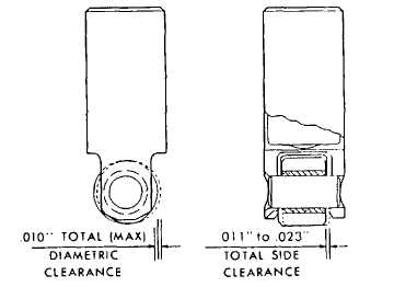
(14) Remove the cam follower from the
fixture and check the side clearance.
The clearance must be 0011 - 0.023
in. (0.28 - 0.58 mm).
(15) Install cam follower as detailed in
INSTALLATION preceding.
2-179
|