|
| |
TM 5-4210-220-34
2-19.
ENGINE - Continued
b.
Steering Pump Drive Installation
(1)
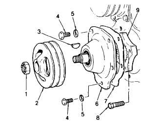
Install drive plate (9) in engine and secure with
bolts (8). Torque to 30 ft lb (41 Nm). Remove
cloth from housing opening.
(2)
Affix a new gasket (7) to the mounting flange
on the retainer (6).
(3)
Position the retainer and shaft assembly
against the housing. Rotate the shaft slightly,
if necessary, to permit the teeth of the shaft to
mesh with the teeth in the accessory drive
plate. Secure the retainer to the housing with
five bolts (4) and lockwashers (5). Tighten the
bolts to 30 ft lb (41 Nm).
(4)
Install the key (3) in the shaft. Then start the pulley (2) on the shaft and tap it into place.
(5)
Install the retaining nut (1) and tighten to 120 ft lb (163 Nm).
(6)
Mount the steering pump as detailed in TM 5-4210-220-12.
c.
Alternator Drive Installation
(1)
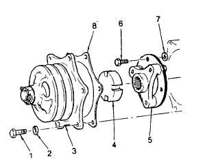
Install the drive hub assembly (5) on the blower
drive gear using new bolts (6) and spacers (7).
(2)
Slip the snap ring over the notched end of tool
J33001 and thread the blower drive shaft onto
the end of the tools.
(3)
Install the shaft and position the blower so the
shaft can be removed and installed.
(4)
Remove the shaft and rotate the blower in 90
deg. Increments reinserting the shaft and
repositioning blower as necessary. Check
alinement for the full 360 deg. rotation of the
blower.
(5)
Insert the drive shaft in the position of least
drag and install the snap ring. The notch in the tool provides sufficient clearance for installation of the
snap ring with needle nose pliers.
(6)
Place a new gasket (8) on the mounting flange of the accessory drive housing.
(7)
Place the slotted drive coupling (4) on the hub of the accessory drive assembly. Aline the slots in the
coupling with the lugs on the drive hub which is attached to the blower drive gear and carefully position
the accessory drive against the flywheel housing.
(8)
Secure the accessory drive assembly (3) to the flywheel housing with bolts (1) and lockwashers (2).
(9)
Mount the alternator and associated mounting brackets to the engine as detailed in TM 5-4210-220-12.
2-169
|


