|
| |
TM 5-4210-220-34
2-19.
ENGINE - Continued
c.
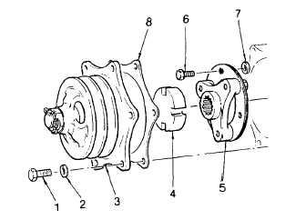
Alternator Drive Removal
(1)
Remove alternator and associated
mounting brackets (see TM 5-4210-
220-12).
(2)
Remove the bolts (1) and lockwashers
(2) and carefully withdraw the pulley
assembly (3), drive coupling (4) and
gasket (8).
(3)
Remove
the
blower
drive
shaft
retaining ring. Thread a No. 10-32
screw in the tapped hole and withdraw
the blower drive shaft. Remove the
screw used to withdraw the shaft.
(4)
If necessary unscrew the three bolts
and withdraw the drive hub assembly
(5). Use extreme care so as not to
drop spacers (7) into gear train.
(5)
Discard the spacers and bolts. When installing drive hub assembly use new type bolts.
d.
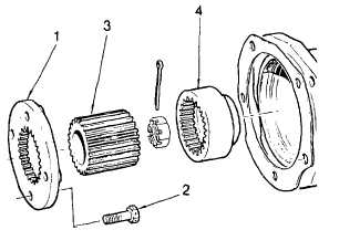
Rear Accessory Drive Assembly (Direct Drive) Removal
NOTE
A
single
direct-drive
assembly
is
installed. It is used to drive the air
compressor.
(1)
Remove air compressor as detailed in
TM 5-4210-220-12.
(2)
Remove the drive coupling (3) out of
the flywheel housing opening. (Drive
hub
(4)
is
retained
with
air
compressor.)
(3)
Place a clean, lintless cloth in the
flywheel housing opening (under the
accessory drive plate) to prevent bolts
from accidentally falling into the gear
train.
(4)
Remove the four bolts (2) and
withdraw the drive plate (1).
2-167
|


