|
| |
TM 5-4210-220-34
2-15.
WATER TANK ASSEMBLY - Continued
2-15.3
Tank Rear Fill Valve.
This task covers:
a.
Replacement
b.
Repair
TOOLS
All Air Tanks Drained
Tool Kit, -General Mechanic, Automotive,
(see TM 5-4210-220-12)
NSN 5180-00-177-7033
Water Tank Drained
(see TM 5-4210-220-12)
EQUIPMENT CONDITION
Main Engine Shutdown
MATERIALS/PARTS
(see TM 5-4210-220-12)
14, Appendix B Gasket Eliminator
APU Shutdown (see TM 5-4210-220-12)
22, Appendix B Pipe Sealant
Batteries Disconnected
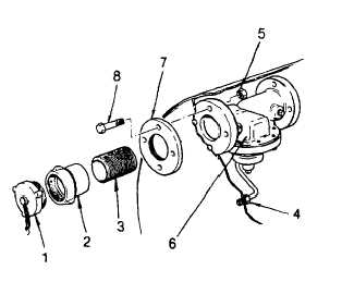
FIG 113-2.5 Automatic Tank Fill Valve
(see TM 5-4210-220-12)
310591 Locknut, 5/8-11
PERSONNEL REQUIRED - 2
REPLACEMENT
(1) From the rear of the truck remove cap (1),
swivel adaptor (2), and nipple (3).
(2) From inside the tank, disconnect air line
fitting (4).
(3) While supporting valve (6) from the inside
and the flange (7) and capscrews (8) from
the outside, remove nuts (5).
NOTE
Flange (7) cannot be removed from the
space between hose body and tank
without
removing
the
hose
body.
Therefore, when the valve is removed,
the flange, attached to tank with gasket
eliminator,
together with capscrews (8) should be left in place and supported until new valve is installed.
(4) Remove valve from tank and support flange (7) to keep it in place and sealed to tank wall.
(5) If seal between tank and flange (7) is broken, clean flange and tank surface. When ready to install new valve
(6) apply gasket eliminator (item 14, Appendix B) to mating surface of flange (7) and reinstall it together with
capscrews (8).
(6) Inspect new valve for shipping damage and apply gasket eliminator (item 14, Appendix B) on flange to mate
with tank. The directional flow arrow on valve body should point toward tank cavity.
(7)
Apply gasket eliminator (item 14, Appendix B) to capscrews (8) where these protrude tank wall. Install valve
(6) on capscrews. Install and tighten nuts (5) to 135 ft lb (180 Nm).
2-146
|