|
| |
TM 5-4210-220-12
4-32. FRONT AXLE-Continued
4-32.5 Brake Assembly-Continued
(19)
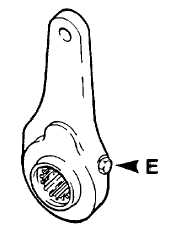
Depress slack adjuster locking sleeve and turn adjuster
nut (E) with a wrench at least one turn clockwise and
counterclockwise. If binding is observed, replace slack
adjuster.
(20)
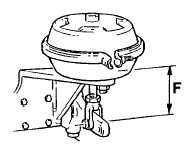
If brake chamber (24) is replaced, adjust clevis position
on push rod so that distance (F) from chamber to center
of clevis pin holes equals 2 5/8 - 1/16 in. (66.7 - 1.6 mm).
CAUTION
Do not reuse a brake drum if the diameter of the
bore exceeds the manufacturers recommended
maximum or the total indicated runout exceeds
0.020 in. (0.51 mm).
(21)
Inspect brake drum for cracks, heat-checks, glazing,
grooving, runout and out-of-round If brake drum is
cracked it must be replaced. If drum is glazed, grooved,
out-of-round, etc., it may be turned in a lathe and reused
provided the maximum diameter of the bore is less than
the figure stamped inside the drum.
INSTALLATION
(1)
If disassembled, assemble air chamber (24) and bracket
(17) using washers and nuts (20 and 21). Be sure air
hose port in brake chamber faces away from ball socket.
Tighten nuts to 170 ft lb (230 Nm).
(2)
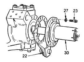
If replaced, install new brake spider (22) and wheel spindle (30) using hardened washer (27) and bolts
(23). Apply threadlock liquid (Item 29, Appendix E) to bolt threads. Install and tighten bolts to 200 ft lb
(270 Nm).
4-608
|


